Difference between revisions of "Examples of Communication Systems/xDSL Systems"
m (Text replacement - "analyse" to "analyze") |
|||
| Line 2: | Line 2: | ||
{{Header | {{Header | ||
|Untermenü=DSL – Digital Subscriber Line | |Untermenü=DSL – Digital Subscriber Line | ||
| − | |Vorherige Seite= | + | |Vorherige Seite=General Description of DSL |
| − | |Nächste Seite=xDSL | + | |Nächste Seite=xDSL as Transmission Technology |
}} | }} | ||
| − | == | + | ==Reference models== |
<br> | <br> | ||
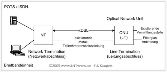
| − | + | Based on the following general ITU reference model, it can be quickly seen that xDSL is physically a pure access transmission technology that is only used in the local loop network area between the fiber termination point and the network termination at the end customer. | |
| − | [[File:P_ID1916__Bei_T_2_2_S1_v1.png|right|frame| | + | [[File:P_ID1916__Bei_T_2_2_S1_v1.png|right|frame|xDSL reference model of the ITU]] |
| − | + | The basic elements of the xDSL standard are: | |
| − | * | + | *the network termination $\rm$, |
| − | * | + | *a subscriber line $\rm $ and |
| − | * | + | *the line termination $\rm $. |
| − | + | There is a lot of freedom for network operators in implementing this reference model in practice. What all previous implementations have in common is that they use existing metallic subscriber lines. | |
<br clear=all> | <br clear=all> | ||
{{GraueBox|TEXT= | {{GraueBox|TEXT= | ||
| − | $\text{ | + | $\text{Examples 1:}$ |
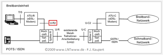
| − | In | + | In an example, the configuration most frequently encountered in Germany is shown according to the graphic. To note: |
| − | [[File:P_ID1919__Bei_T_2_2_S1b_v2.png|right|frame| | + | [[File:P_ID1919__Bei_T_2_2_S1b_v2.png|right|frame|Reference model according to $\text{1TR112_U-R2-V7.0 DTAG}$]] |
| − | * | + | *In all xDSL variants deployed today, the data service converted in the modems is combined with the telephone service. This allows transmission over the existing telephone network. |
| − | * | + | *The splitter splits the signal on both sides of the subscriber line. |
| − | * | + | *An important interface is designated $\rm U-R2$ (red marking). This was standardized in Germany in 2001 by Deutsche Telekom AG in order to be able to use any modems on the subscriber side. This means that the customer is no longer dependent on his provider's xDSL modem}}. |
| − | == | + | ==Overview and common features of all xDSL systems== |
<br> | <br> | ||
| − | + | The technical realization of an xDSL system involves many system components, which can be distributed over several localities. There is a wide range of realization options. To summarize: | |
| − | * | + | *The systems for ADSL and VDSL shown below represent the most common implementation at the present time (end of 2009). <br>Data transport at the protocol level is based on the $\rm ATM$ technology (''Asynchronous Transfer Mode''). |
| − | * | + | *Despite a large data overhead, ATM still offers advantages over Ethernet in terms of guaranteed quality of service (QoS), i.e. effective bit rate, low delay and jitter. |
| − | *Ethernet | + | *Ethernet, on the other hand, enables very high data transmission rates, especially through the "10 Gbit/s Ethernet" and "100 Gbit/s Ethernet" (''Metro Ethernet'') variants. ATM, on the other hand, is more suitable for lower data rates. |
| − | + | There are currently numerous discussions about whether ATM should be replaced by 10 Gbit/s Ethernet in the course of ''Next Generation Network''. However, upgrading the backbone from ATM to Ethernet represents a not inconsiderable investment. | |
{{BlaueBox|TEXT= | {{BlaueBox|TEXT= | ||
| − | $\text{ | + | $\text{Summary:}$ |
| − | + | As mentioned in the chapter [[Examples_of_Communication_Systems/General_Description_of_DSL|"General Description of DSL"]] , the most commonly deployed xDSL variants are. | |
| − | *$\rm ADSL$ | + | *$\rm ADSL$ and $\rm ADSL2$ respectively $\rm ADSL2+$ |
| − | *$\rm VDSL(1)$ | + | *$\rm VDSL(1)$ and $\rm VDSL(2)$ |
| − | + | defined in such a way that simultaneous operation of '''POTS''' (''Plain Old Telephone Service'') or '''ISDN''' (''Integrated Services Digital Network'') on the same line is possible at any time. This is also the basis of the further descriptions}}. | |
==ADSL – Asymmetric Digital Subscriber Line == | ==ADSL – Asymmetric Digital Subscriber Line == | ||
<br> | <br> | ||
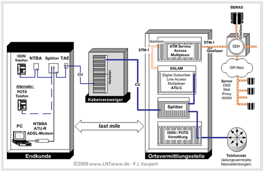
| − | + | The physical network termination is in the local exchange in the ADSL modem (''ADSL Transmission Unit Central Office'', $\rm ATU-C)$. Before that, in the ''splitter'' the low-frequency telephony spectrum is still separated from the higher-frequency ADSL spectrum by low-pass and high-pass filtering. | |
| − | [[File:P_ID1918__Bei_T_2_2_S3_v2.png|center|frame| | + | [[File:P_ID1918__Bei_T_2_2_S3_v2.png|center|frame|Modeling of an ADSL connection from the end customer to the local exchange]] |
| − | + | The graphic shows an ADSL connection from the end customer to the local exchange, which is described very briefly below. The reverse data connection paths are in each case mirror images. | |
| − | * | + | *The splitter forwards the telephone signals to the ISDN/POTS exchange and the ADSL signals to the ''Digital Subscriber Line Access Multiplexer'' (DSLAM), in which the ''ADSL Transmission Unit Central Office'' (ATU-C) is implemented as a plug-in card. |
| − | * | + | *The DSLAM bundles many ADSL connections and forwards the data after decoding at the ATM level via optical fiber to the ''ATM Service Access Multiplexer'' . This sends the data from all DSLAMs over the backbone to the ''Broadband Remote Access Server'' (BBRAS). |
| − | * | + | *The BBRAS terminates the point-to-point protocol data link and forwards the IP packets via routers to the destination. The backbone consists of optical components based on the SDH standard (''Synchronous Digital Hierarchy''). |
| − | * | + | *The splitter connected to the ''telecommunications connection unit'' (TAE) separates the signals. The telephone signals are routed to the telephony terminals or to the NTBA, the ADSL signals to the modem (''ADSL Transmission Unit Remote'', ATU-R). The modem decodes and forwards the binary data to the connected terminals. |
| − | + | During initialization of the ADSL connection, $\rm ATU-C$ and $\rm ATU-R$ perform a so-called "training" in which relevant system parameters such as data rate, interleaved and fast mode, etc. are determined depending on the line conditions. The parameters negotiated in this process are retained until the next check and synchronization. For the transmission of administrative data (''overhead''), 32 kbit per frame are statically reserved in the ADSL systems. | |
| − | ==ADSL2 | + | ==ADSL2 and ADSL2plus== |
<br> | <br> | ||
| − | + | These two system variants are further developments of ADSL: | |
| − | * | + | *The enhanced system variant ''Asymmetric Digital Subscriber Line Transceivers 2'' $\rm (ADSL2)$ was specified in 2002 with the publication of ITU Recommendations '''G.992.3''' and '''G.992.4''' . |
| − | *2003 | + | *2003 was followed by the ITU recommendation '''G.992.5''': ''Extended-bandwidth ADSL2'' $\rm (ADSL2+)$. |
| − | + | Compared to ADSL, the following changes occurred: | |
| − | * | + | *In ADSL2, the ''Seamless Rate Adaption'' (SRA) was included in the standard. This allows transmission parameters to be changed during operation with time-variant channel quality without loss of synchronization. |
| − | * | + | *For this purpose, ATU-C and ATU-R periodically check the ''Signal–to–Noise Ratio'' (SNR) of the transmission channels. If a channel in use deteriorates, the receiver notifies the transmitter of the new data rate and transmission level. After a subsequent ''sync flag'' the parameters are adopted. |
| − | * | + | *ADSL2 systems also offer a wide range of diagnostic options even without the modems having been synchronized, a feature that is particularly important for troubleshooting, error analysis and error correction. |
| − | * | + | *In addition, ADSL2 provides the ability to reduce transmit levels when SNR is sufficient, thereby minimizing crosstalk and increasing throughput in the trunk cable. This ''power cutback'' can be initiated not only by the DSLAM, but also by the ATU-R. |
| − | * | + | *In ADSL2, the number of overhead bits is no longer fixed, but can vary between 4 and 32 kbit. This increase in the user data bit rate of up to 28 kbit/s per data frame is all the more important the longer the distance between the modem and the DSLAM. |
| − | + | As a result, ADSL2 systems achieve a transmission rate of more than 8 Mbit/s (up to 12 Mbit/s) downstream and more than 800 kbit/s (up to 3.5 Mbit/s) upstream. | |
| − | + | With ADSL2+, the transmission rate in the downstream is doubled again; the maximum rate is theoretically 25 Mbit/s. | |
==VDSL – Very–high–speed Digital Subscriber Line == | ==VDSL – Very–high–speed Digital Subscriber Line == | ||
<br> | <br> | ||
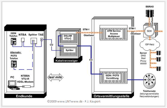
| − | + | In terms of the basic structure of their components, VDSL systems are identical to ADSL systems, with the only exception that the relocation of the splitter and the DSLAM from the local exchange to a cable branch makes the last section between the network operator and the customer - the so-called ''last mile'' - shorter. This measure was necessary because VDSL can only exploit its advantage - the greater transmission speed - over very short distances due to the attenuation of the higher frequencies, which increases sharply with line length. | |
| − | DSLAM | + | DSLAM and BBRAS are still connected via STM-1 interfaces. Therefore, the route between the local exchange and the cable branch must now also be laid with optical fiber. |
| − | [[File:P_ID1920__Bei_T_2_2_S5_v1.png|center|frame| | + | [[File:P_ID1920__Bei_T_2_2_S5_v1.png|center|frame|Modeling of a VDSL connection from the end customer to the local exchange]] |
| − | + | A distinction is made between two alternative VDSL variants: | |
| − | * | + | *the $\rm VDSL(1)$ system based on [[Modulation_Methods/Quadrature_Amplitude_Modulation|"QAM"]] (quadrature amplitude modulation), which is predominantly deployed in Asia, and. |
| − | + | *the $\rm VDSL(2)$ system based on [[Modulation_Methods/Further_OFDM_Applications#A_brief_description_of_DSL_-_Digital_Subscriber_Line|"DMT"]] (''Discrete Multitone Transmission''). | |
| − | VDSL(1) | + | VDSL(1) systems were never deployed in Germany because of their inadequate ability to provide audio/video, telephony and Internet (''triple play'') with sufficient quality of service. Instead, the VDSL(2) standard was established immediately: Because of higher performance and greater range, the better quality of service as well as the reusability of ADSL(2+) infrastructure. |
{{BlaueBox|TEXT= | {{BlaueBox|TEXT= | ||
| − | $\text{ | + | $\text{Summary:}$ |
| − | + | Following are a few characteristics of the $\rm VDSL(2)$ system: | |
| − | *VDSL(2) | + | *VDSL(2) has achieved a maximum transmission rate of 50 to 100 Mbps since 2006, depending on the standard used. |
| − | * | + | *The specified VDSL(2) transmission bandwidth of 30 MHz was considered the maximum reasonable bandwidth in 2009. |
| − | * | + | *By 2011, with complementary measures such as ''Dynamic Spectrum Management'' and ''Advanced Codes'' total transmission rates of up to 280 Mbit/s were expected for short line lengths (up to 300 meters).}} |
Revision as of 15:30, 5 March 2023
Contents
- 1 Reference models
- 2 Overview and common features of all xDSL systems
- 3 ADSL – Asymmetric Digital Subscriber Line
- 4 ADSL2 and ADSL2plus
- 5 VDSL – Very–high–speed Digital Subscriber Line
- 6 DSL–Internetzugang aus Sicht der Kommunikationsprotokolle
- 7 Komponenten eines DSL–Internetzugangs
- 8 Aufgaben zum Kapitel
Reference models
Based on the following general ITU reference model, it can be quickly seen that xDSL is physically a pure access transmission technology that is only used in the local loop network area between the fiber termination point and the network termination at the end customer.
The basic elements of the xDSL standard are:
- the network termination $\rm$,
- a subscriber line $\rm $ and
- the line termination $\rm $.
There is a lot of freedom for network operators in implementing this reference model in practice. What all previous implementations have in common is that they use existing metallic subscriber lines.
$\text{Examples 1:}$ In an example, the configuration most frequently encountered in Germany is shown according to the graphic. To note:
- In all xDSL variants deployed today, the data service converted in the modems is combined with the telephone service. This allows transmission over the existing telephone network.
- The splitter splits the signal on both sides of the subscriber line.
- An important interface is designated $\rm U-R2$ (red marking). This was standardized in Germany in 2001 by Deutsche Telekom AG in order to be able to use any modems on the subscriber side. This means that the customer is no longer dependent on his provider's xDSL modem
.
Overview and common features of all xDSL systems
The technical realization of an xDSL system involves many system components, which can be distributed over several localities. There is a wide range of realization options. To summarize:
- The systems for ADSL and VDSL shown below represent the most common implementation at the present time (end of 2009).
Data transport at the protocol level is based on the $\rm ATM$ technology (Asynchronous Transfer Mode). - Despite a large data overhead, ATM still offers advantages over Ethernet in terms of guaranteed quality of service (QoS), i.e. effective bit rate, low delay and jitter.
- Ethernet, on the other hand, enables very high data transmission rates, especially through the "10 Gbit/s Ethernet" and "100 Gbit/s Ethernet" (Metro Ethernet) variants. ATM, on the other hand, is more suitable for lower data rates.
There are currently numerous discussions about whether ATM should be replaced by 10 Gbit/s Ethernet in the course of Next Generation Network. However, upgrading the backbone from ATM to Ethernet represents a not inconsiderable investment.
$\text{Summary:}$ As mentioned in the chapter "General Description of DSL" , the most commonly deployed xDSL variants are.
- $\rm ADSL$ and $\rm ADSL2$ respectively $\rm ADSL2+$
- $\rm VDSL(1)$ and $\rm VDSL(2)$
defined in such a way that simultaneous operation of POTS (Plain Old Telephone Service) or ISDN (Integrated Services Digital Network) on the same line is possible at any time. This is also the basis of the further descriptions
.
ADSL – Asymmetric Digital Subscriber Line
The physical network termination is in the local exchange in the ADSL modem (ADSL Transmission Unit Central Office, $\rm ATU-C)$. Before that, in the splitter the low-frequency telephony spectrum is still separated from the higher-frequency ADSL spectrum by low-pass and high-pass filtering.
The graphic shows an ADSL connection from the end customer to the local exchange, which is described very briefly below. The reverse data connection paths are in each case mirror images.
- The splitter forwards the telephone signals to the ISDN/POTS exchange and the ADSL signals to the Digital Subscriber Line Access Multiplexer (DSLAM), in which the ADSL Transmission Unit Central Office (ATU-C) is implemented as a plug-in card.
- The DSLAM bundles many ADSL connections and forwards the data after decoding at the ATM level via optical fiber to the ATM Service Access Multiplexer . This sends the data from all DSLAMs over the backbone to the Broadband Remote Access Server (BBRAS).
- The BBRAS terminates the point-to-point protocol data link and forwards the IP packets via routers to the destination. The backbone consists of optical components based on the SDH standard (Synchronous Digital Hierarchy).
- The splitter connected to the telecommunications connection unit (TAE) separates the signals. The telephone signals are routed to the telephony terminals or to the NTBA, the ADSL signals to the modem (ADSL Transmission Unit Remote, ATU-R). The modem decodes and forwards the binary data to the connected terminals.
During initialization of the ADSL connection, $\rm ATU-C$ and $\rm ATU-R$ perform a so-called "training" in which relevant system parameters such as data rate, interleaved and fast mode, etc. are determined depending on the line conditions. The parameters negotiated in this process are retained until the next check and synchronization. For the transmission of administrative data (overhead), 32 kbit per frame are statically reserved in the ADSL systems.
ADSL2 and ADSL2plus
These two system variants are further developments of ADSL:
- The enhanced system variant Asymmetric Digital Subscriber Line Transceivers 2 $\rm (ADSL2)$ was specified in 2002 with the publication of ITU Recommendations G.992.3 and G.992.4 .
- 2003 was followed by the ITU recommendation G.992.5: Extended-bandwidth ADSL2 $\rm (ADSL2+)$.
Compared to ADSL, the following changes occurred:
- In ADSL2, the Seamless Rate Adaption (SRA) was included in the standard. This allows transmission parameters to be changed during operation with time-variant channel quality without loss of synchronization.
- For this purpose, ATU-C and ATU-R periodically check the Signal–to–Noise Ratio (SNR) of the transmission channels. If a channel in use deteriorates, the receiver notifies the transmitter of the new data rate and transmission level. After a subsequent sync flag the parameters are adopted.
- ADSL2 systems also offer a wide range of diagnostic options even without the modems having been synchronized, a feature that is particularly important for troubleshooting, error analysis and error correction.
- In addition, ADSL2 provides the ability to reduce transmit levels when SNR is sufficient, thereby minimizing crosstalk and increasing throughput in the trunk cable. This power cutback can be initiated not only by the DSLAM, but also by the ATU-R.
- In ADSL2, the number of overhead bits is no longer fixed, but can vary between 4 and 32 kbit. This increase in the user data bit rate of up to 28 kbit/s per data frame is all the more important the longer the distance between the modem and the DSLAM.
As a result, ADSL2 systems achieve a transmission rate of more than 8 Mbit/s (up to 12 Mbit/s) downstream and more than 800 kbit/s (up to 3.5 Mbit/s) upstream.
With ADSL2+, the transmission rate in the downstream is doubled again; the maximum rate is theoretically 25 Mbit/s.
VDSL – Very–high–speed Digital Subscriber Line
In terms of the basic structure of their components, VDSL systems are identical to ADSL systems, with the only exception that the relocation of the splitter and the DSLAM from the local exchange to a cable branch makes the last section between the network operator and the customer - the so-called last mile - shorter. This measure was necessary because VDSL can only exploit its advantage - the greater transmission speed - over very short distances due to the attenuation of the higher frequencies, which increases sharply with line length.
DSLAM and BBRAS are still connected via STM-1 interfaces. Therefore, the route between the local exchange and the cable branch must now also be laid with optical fiber.
A distinction is made between two alternative VDSL variants:
- the $\rm VDSL(1)$ system based on "QAM" (quadrature amplitude modulation), which is predominantly deployed in Asia, and.
- the $\rm VDSL(2)$ system based on "DMT" (Discrete Multitone Transmission).
VDSL(1) systems were never deployed in Germany because of their inadequate ability to provide audio/video, telephony and Internet (triple play) with sufficient quality of service. Instead, the VDSL(2) standard was established immediately: Because of higher performance and greater range, the better quality of service as well as the reusability of ADSL(2+) infrastructure.
$\text{Summary:}$ Following are a few characteristics of the $\rm VDSL(2)$ system:
- VDSL(2) has achieved a maximum transmission rate of 50 to 100 Mbps since 2006, depending on the standard used.
- The specified VDSL(2) transmission bandwidth of 30 MHz was considered the maximum reasonable bandwidth in 2009.
- By 2011, with complementary measures such as Dynamic Spectrum Management and Advanced Codes total transmission rates of up to 280 Mbit/s were expected for short line lengths (up to 300 meters).
DSL–Internetzugang aus Sicht der Kommunikationsprotokolle
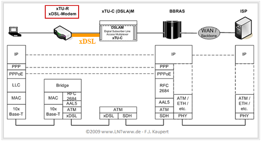
Manche xDSL–Modems bieten eine Ethernet–Schnittstelle zum Anschluss der Datenendgeräte an und eine transparente Verbindung zur Gegenstelle, basierend auf dem Internet-Protokoll. Anzumerken ist:
- Diese Option wird durch die LAN–Emulation (RFC2684) sowie das ATM Adaption Layer Protocol (AAL5) ermöglicht. Der Ethernet–Datenstrom wird dazu auf ATM umgesetzt.
- Damit entfällt die Installation von ATM–Geräten und vorhandene Ethernet–Hardware kann verwendet werden, was die xDSL–Konfiguration beim Kunden wesentlich vereinfacht.
- Die ATM–Verbindung reicht mindestens bis zum Broadband Remote Access Server (BBRAS) und wird dort je nach Backbone–Datenübertragungssystem umgesetzt oder direkt weitergeführt.
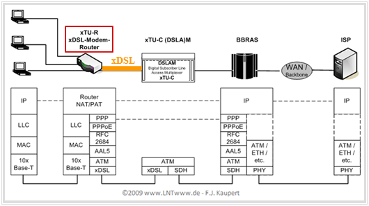
Die folgenden Grafiken zeigen die Kommunikation bei einer Internetverbindung nach dem OSI–Modell, wobei $\rm xDSL$ nur zwischen der $\rm xTU-R$ auf Kundenseite und der $\rm xTU-C$ auf Anbieterseite eingesetzt wird (braune Hinterlegung).
Für die erste Grafik wird als xTU–R ein $\rm xDSL–Modem$ angenommen.
In der zweiten Grafik wird als xTU–R–Schnittstelle ein $\rm xDSL–Router$ verwendet.
- Dieser ermöglicht den Anschluss mehrerer Endgeräte in einem Netzwerk mit gemeinsam genutzter xDSL–Leitung.
- Hier initialisiert anstelle des Modems ein Router die Point–to–Point–Protocol–over–Ethernet–Verbindung.
Komponenten eines DSL–Internetzugangs
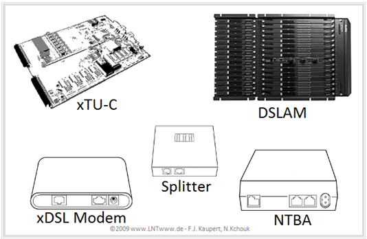
Abschließend werden notwendige Komponenten für einen DSL–Anschluss aufgelistet. Die Grafik zeigt Beispiele hierfür, meist von der Deutschen Telekom.
$\rm NTBA$: Die allgemein übliche Bezeichnung ist Network Termination for ISDN Basic Rate Access. Bei der deutschen Telekom steht der Begriff auch für "Netzterminator Basis Anschluss". Aufgaben des NTBA sind:
- Mit Hilfe einer Gabelschaltung und einer Echokompensation wird die zweidrahtige UK0–Schnittstelle auf der Anbieterseite in die vierdrahtige S0–Schnittstelle der Teilnehmerseite umgesetzt.
- Außerdem bewerkstelligt der NTBA die ISDN–Codeumsetzung vom MMS43–Code $\rm (U_{K0}$–Bus) auf den modifizierten AMI–Code $\rm (S_{0}$–Bus).
$\rm xTU–R$: Die Abkürzung steht für xDSL Transceive Unit – Remote und bezeichnet die teilnehmerseitige xDSL–Einheit. Bei der Deutschen Telekom – schon immer bekannt für besondere Namensgebungen – ist auch die Bezeichnung Netzwerkterminationspunkt Breitbandanschluss (NTBBAE) üblich.
- Wegen der großen Verbreitung von Ethernet weisen heutige xDSL–Modems und Router zur Anbindung der Datenendeinrichtungen meist nur noch einen Ethernet–Anschluss auf. Ursprünglich dienten sie zum teilnehmerseitigen Anschluss von ATM–Datenendgeräten.
- Deshalb muss diese Einheit auch die Funktion einer Layer–2–Bridge übernehmen, um Ethernet über ATM zur Terminierung an den Broadband Remote Access Server (BBRAS) übertragen zu können.
$\rm xDSL–Modem$: Bei dieser Funktionseinheit wird die Datenverbindung vom/zum Datenendgerät durch ein Point–to–Point–Protokoll (PPP) über eine PPP over Ethernet–Verbindung (PPPoE) initialisiert und vom BBRAS terminiert. Es kommen nur Datenendgerät in Frage, die separat eine Datenverbindung über PPP aufbauen können.
$\rm xDSL–Modem–Router$: Dieser initialisiert die Datenverbindung über PPP und setzt die Adressen auf IP–Ebene durch. Dadurch können mehrere Endgeräte angeschlossen werden und es ist ein interner Datenaustausches zwischen diesen möglich, ohne sich in diese separat einwählen zu müssen.
$\rm Splitter$: Dieser ist im Prinzip eine Kombination aus Hoch– und Tiefpass mit drei Schnittstellen, die die Trennung der hochfrequenten xDSL–Datensignale (oberhalb von 138 kHz) von den niederfrequenten POTS– bzw. ISDN–Telefonsignalen (unterhalb von 120 kHz) übernimmt, bzw. deren Kombination.
- Diese Breitbandanschlusseinheit (BBAE) – wie sie im Telekom–Jargon auch heißt – ist nichts anderes als eine Frequenzweiche.
- Auf Seite der Teilnehmeranschlussleitung liegt die Summe der Signale an, während sowohl beim Kunden als auch auf der Anbieterseite die xDSL–Daten und die POTS/ISDN-Signale jeweils durch einen Splitter voneinander getrennt sind.
$\rm xTU-C$: Die Abkürzung steht für xDSL Transceive Unit – Central office. Sie ist die anbieterseitige xDSL–Einheit und wird meist als Leiterplatteneinschub (Linecard) für den DSLAM realisiert. Er wird manchmal auch als Netzwerkterminationspunkt Breitbandanschluss (NTBBAE) bezeichnet. Der xTU–C terminiert die physikalischen Endkunden–xDSL–Teilnehmeranschlüsse, moduliert teilnehmerseitig den ATM–Bitdatenstrom und demoduliert anbieterseitig das xDSL–Signal.
$\rm DSLAM$: Die Abkürzung steht für Digital Subscriber Line Access Multiplexer. Fachleute verwenden für den DSLAM, den es in verschiedenen Ausführungen gibt, auch die Bezeichnung „MXBBA”. In der einfachsten Form terminiert er mit seinen xTU–C–Linecards die physikalischen Teilnehmeranschlüsse. In erweiterter Form ist im DSLAM auch ein ATM Service Access Multiplexer integriert.
- Aufgabe des DSLAM ist es, die ATM–Bitströme der Teilnehmeranschlussleitungen zu bündeln und konzentriert im Multiplexverfahren über eine STM–1–Glasfaserschnittstelle ins Anbieternetz weiterzuleiten.
- STM ist ein SDH–Übertragungsstandard zum Multiplexen von optischen Kanälen und steht für Synchronous Transport Module. STM–1 ermöglicht eine Bitrate von bis zu 155.52 Mbit/s, STM–64 bis zu fast 10 Gbit/s.
Aufgaben zum Kapitel
Aufgabe 2.2Z: DSL–Internetanschluss
