Difference between revisions of "Modulation Methods/Synchronous Demodulation"
m |
m |
||
| Line 41: | Line 41: | ||
:$$H_{\rm E}(f = 0) = 0.$$ | :$$H_{\rm E}(f = 0) = 0.$$ | ||
| − | *The color assignment in the diagram (USB blue, LSB green, carrier red) shows that the synchronous demodulator uses both the $\rm USB$ and the $\rm LSB$ for signal reconstruction. | + | *The color assignment in the diagram (USB in blue, LSB in green, carrier in red) shows that the synchronous demodulator uses both the $\rm USB$ and the $\rm LSB$ for signal reconstruction. |
<br clear=all> | <br clear=all> | ||
==Prerequisites for the application of a synchronous demodulator== | ==Prerequisites for the application of a synchronous demodulator== | ||
Revision as of 16:18, 25 March 2022
Contents
- 1 Block diagram and time domain representation
- 2 Description in the frequency domain
- 3 Prerequisites for the application of a synchronous demodulator
- 4 Influence of a frequency offset
- 5 Influence of a phase offset
- 6 Influence of linear channel distortions
- 7 Influence of noise interference
- 8 Calculating the noise power
- 9 Relationship between the powers from source signal and transmitted signal
- 10 Sink SNR and the performance parameter
- 11 Exercises for the Chapter
Block diagram and time domain representation
Modulation at the transmitter only makes sense, if it is possible to reverse this signal conversion at the receiver end, ideally without loss of information. In any form of amplitude modulation - be it double sideband (DSB) or single sideband (SSB), with or without a carrier signal - the so-called synchronous demodulator fulfils this task.
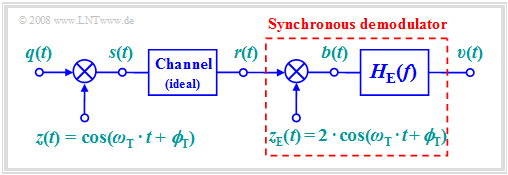
The following should be noted with regard to the block diagram on the right:
- For modulation, we will focus on "DSB–AM without a carrier" $($modulation depth $m → ∞)$. However, synchronous demodulation is also applicable in "DSB–AM with carrier".
- Let the channel be ideal and the distortions negligible, that the received signal $r(t)$ is identical to the transmitted signal $s(t)$:
- $$r(t) = s(t) = q(t) \cdot \cos(\omega_{\rm T} \cdot t + \phi_{\rm T})\hspace{0.05cm}.$$
- At the receiver, $r(t)$ is first multiplied by the receiver-side carrier $z_{\rm E}(t)$, which is identical shaped to the transmitter-side carrier $z(t)$ but larger by a factor of $2$:
- $$z_{\rm E}(t) = 2 \cdot \cos(\omega_{\rm T} \cdot t + \phi_{\rm T})\hspace{0.05cm}.$$
- The result of the multiplication is the signal $b(t)$. Considering the trigonometric transformation $\cos^2(α) = 1/2 · \big [1 + \cos(2α)\big ]$ we get
- $$b(t) = r(t) \cdot z_{\rm E}(t) = 2 \cdot q(t) \cdot \cos^2(\omega_{\rm T} \cdot t + \phi_{\rm T}) = q(t) + q(t) \cdot \cos(2 \cdot \omega_{\rm T} \cdot t + 2\cdot \phi_{\rm T})\hspace{0.05cm}.$$
- The second term is in the range around twice the carrier frequency $f_{\rm T}$. If the signal bandwidth is $B_{\rm NF} < f_{\rm T}$, which is always true in practice, this component can be suppressed by a low-pass filter $H_{\rm E}(f)$ with suitable dimensions, and we obtain
- $$v(t) = q(t).$$
Description in the frequency domain
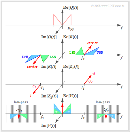
Assuming an even source signal $q(t)$ ⇒ with a real spectrum $Q(f)$ and a sinusoidal carrier $z(t)$, the imaginary transmitted spectrum $S(f)$ is obtained according to the second plot, where $A_{\rm T} ≠ 0$ also takes into account the DSB-AM with a carrier (shown by the red Dirac delta function). Because the channel is ideal, $R(f) = S(f)$.
The operation of the synchronous demodulator can be explained in the frequency domain as follows:
- The receiver-side carrier signal $z_{\rm E}(t) = 2 · z(t) = 2 · \sin(ω_{\rm T} · t)$ leads to two Dirac delta functions in the spectral domain at $\pm f_{\rm T}$ with weights $\pm \rm j$. The negative imaginary part occurs at $f = +f_{\rm T}$.
- The multiplication $b(t) = r(t) · z_{\rm E}(t)$ corresponds to the convolution of the associated spectral functions. The result is shown in the sketch below, if the influence of the subsequent low-pass (hatching) is disregarded:
- $$B(f) = R(f) \star Z_{\rm E}(f)\hspace{0.05cm}.$$
- Convolution of the Dirac function $ - {\rm j} \cdot δ(f – f_{\rm T})$ with the wholly imaginary spectrum $R(f)$ leads to completely real spectral components around $f = 0$ and $f = 2f_{\rm T}$. These components are marked with a "plus" on the lower graph.
- The second convolution product ${\rm j} · δ(f + f_{\rm T}) \star R(f)$ yields a low-frequency spectral component around $f = 0$ in addition to a component at $–2f_{\rm T}$. These spectral components are marked with "minus".
- The spectrum after the low-pass $H_{\rm E}(f)$ is $V(f) = Q(f) + A_{\rm T} · δ(f)$. For DSB-AM with a carrier, the interfering DC component can be removed by a lower band limit:
- $$H_{\rm E}(f = 0) = 0.$$
- The color assignment in the diagram (USB in blue, LSB in green, carrier in red) shows that the synchronous demodulator uses both the $\rm USB$ and the $\rm LSB$ for signal reconstruction.
Prerequisites for the application of a synchronous demodulator
The output signal $v(t)$ is identical to the source signal $q(t)$ if the following conditions are satisfied:
- The bandwidth $B_{\rm NF}$ of the source signal is smaller than the carrier frequency $f_{\rm T}$. This restriction is not particularly drastic and is not relevant for practical applications.
- The carrier frequencies of the transmitter and receiver are exactly matched. This requires carrier recovery at the receiver and thus involves some "cost".
- There is also perfect phase synchronicity between the the carrier signals $z(t)$ and $z_{\rm E}(t)$ at the transmitter and receiver end, respectively.
- The channel frequency response $H_{\rm K}(f)$ is ideally equal to $1$ in the passband $f_{\rm T} - B_{\rm NF} ≤ |f| ≤ f_{\rm T} + B_{\rm NF}$. Frequency-independent attenuation or frequency-linear phase (delay) are usually tolerated. Note: The subscript "K" stands for German "Kanal" ⇒ channel).
- The influence of noise and external disturbances is assumed to be negligible in this model. However, even with non-negligible noise, the synchronous demodulator is superior to other demodulators.
- The receiver filter $H_{\rm E}(f)$ is equal to "one" for $|f| ≤ B_{\rm NF}$ and equal to "zero" for $|f| ≥ 2f_{\rm T} - B_{\rm NF}$. The range in between is not relevant (see graph in the previous section). Note: The subscript "E" stands for German "Empfänger" ⇒ "receiver").
- For the modulation method "DSB-AM with carrier", the condition $H_{\rm E}(f = 0) ≡ 0$ must additionally ensure that the carrier added at the transmitter is no longer included in the sink signal.
- The following four sections describe the effects if some of the above conditions are not met.
Influence of a frequency offset
As the name "synchronous demodulator” it only works when there is complete synchronization between the carrier signals of the transmitter and receiver.
On the other hand, if the carrier frequencies differ by a frequency offset $Δ\hspace{-0.05cm}f_{\rm T}$, for example
- $$\begin{align*}z(t) & = 1 \cdot \cos(2 \pi f_{\rm T} \cdot t + \phi_{\rm T})\hspace{0.05cm}, \\ z_{\rm E}(t) & = 2 \cdot \cos(2 \pi (f_{\rm T} + \Delta\hspace{-0.05cm} f_{\rm T}) \cdot t + \phi_{\rm T})\hspace{0.05cm},\end{align*}$$
then we obtain for the sink signal spectrum:
- $$V(f) = {1}/{2}\cdot Q(f + \Delta \hspace{-0.05cm}f_{\rm T}) + {1}/{2}\cdot Q(f - \Delta\hspace{-0.05cm} f_{\rm T}) = Q(f) \star \big[ {1}/{2}\cdot \delta(f + \Delta\hspace{-0.05cm} f_{\rm T}) + {1}/{2}\cdot \delta (f - \Delta \hspace{-0.05cm}f_{\rm T}) \big] \hspace{0.05cm}.$$
This result can be verified in the frequency domain using the sketch on the frequency description page. After transforming the equation to the time domain, we get:
- $$v(t) = q(t) \cdot \cos(2 \pi \cdot \Delta \hspace{-0.05cm}f_{\rm T} \cdot t )\hspace{0.05cm}.$$
$\text{Conclusions:}$
- For DSB-AM (with or without carrier), synchronous demodulation with frequency offset $ \Delta \hspace{-0.05cm}f_{\rm T}$ leads to attenuation distortions, characterized by the "time-dependent factor" $\cos(2 \pi \cdot \Delta \hspace{-0.05cm}f_{\rm T} \cdot t )$.
- The frequency offset $Δ\hspace{-0.05cm}f_{\rm T}$, which is due to inaccuracies in the realization of carrier recovery, is usually very small and ranges from a few Hertz to about $100\text{ Hz}$. In this context, one usually speaks of a "beat".
$\text{Example 1:}$ The graph shows
- a cosine-shaped source signal with frequency $f_{\rm N} = 1\ \rm kHz$
⇒ blue oscillation, and - the sink signal $v(t)$ obtained with a synchronous demodulator
⇒ red curve.
Here, a frequency offset of $Δ\hspace{-0.05cm}f_{\rm T} = 100\ \rm Hz$ was used as a basis. This results in:
- $$\begin{align*}v(t ) & = 1\,{\rm V} \cdot \cos (2 \pi \cdot 1\,{\rm kHz} \cdot t) \cdot \cos (2 \pi \cdot 0.1\,{\rm kHz} \cdot t) =\\ &= 0.5\,{\rm V} \cdot \cos (2 \pi \cdot 0.9\,{\rm kHz} \cdot t) + 0.5\,{\rm V} \cdot \cos (2 \pi \cdot 1.1\,{\rm kHz} \cdot t) \hspace{0.05cm}.\end{align*}$$
From a spectral point of view, the $1\ \rm kHz$ oscillation becomes two superimposed oscillations with frequencies $0.9\ \rm kHz$ and $1.1\ \rm kHz$ with half the amplitude.
- New frequencies occur as a result ⇒ nonlinear distortions.
- In contrast, the transmitted frequency $(1\ \rm kHz)$ is no longer included in $v(t)$ .
Influence of a phase offset
Now, for the transmitter-side and receiver-side carrier signal, it holds that
- $$\begin{align*}z(t) & = 1 \cdot \cos(2 \pi f_{\rm T} t + \phi_{\rm T})\hspace{0.05cm}, \\ z_{\rm E}(t) & = 2 \cdot \cos(2 \pi f_{\rm T} t + \phi_{\rm E})\hspace{0.05cm}.\end{align*}$$
For the signal immediately after multiplication by the phase offset $Δ \mathbf{ϕ_{\rm T} = ϕ_{\rm E} - ϕ_{\rm T} }$, this gives:
- $$b(t) = q(t) \cdot \cos(\omega_{\rm T} \cdot t + \phi_{\rm T}) \cdot 2 \cdot \cos(\omega_{\rm T} \cdot t + \phi_{\rm E})= q(t)\cdot \cos(\Delta \phi_{\rm T}) + q(t) \cdot \cos(2 \cdot \omega_{\rm T} \cdot t + \phi_{\rm E}+ \phi_{\rm T})\hspace{0.05cm}.$$
Thus, taking into account the low-pass filter, the result for the sink signal is:
- $$v(t) = q(t)\cdot \cos(\Delta \phi_{\rm T}) \hspace{0.05cm}.$$
$\text{Conclusions:}$
- For DSB-AM (with or without carrier), synchronous demodulation with phase offset $Δ\mathbf{ϕ_{\rm T} }$ does not lead to distortions,
- but only to a frequency independent attenuation by the time independent factor $\cos(Δ\mathbf{ϕ_{\rm T} })$.
- The reason for this less serious signal change than in the case of a frequency offset is that in this case the time $t$ is missing in the argument of the cosine function.
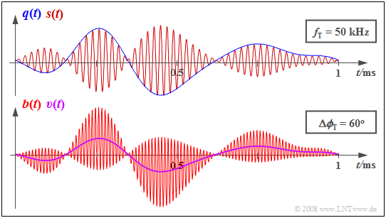
$\text{Example 2:}$ The diagram shows
- the signals $q(t)$ and $s(t)$ at the transmitter above,
- and the receiver-side signals $b(t)$ and $v(t)$ below.
Due to the phase offset of $Δ \mathbf{ϕ_{\rm T} } = π/3\ (60^\circ)$, the sink signal $v(t)$ is only half the size of the source signal $q(t)$.
However, the waveform of $q(t)$ is preserved in the output signal $v(t)$.
Influence of linear channel distortions
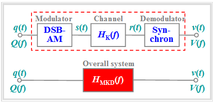
In the section Attenuation distortions of the book "Linear and Time Invariant Systems" it was already suggested that the entire communication system – consisting of the $\rm M$odulator, the channel $($⇒ German: $\rm K$anal$)$ and the $\rm D$emodulator – can be completely described by the resulting frequency response $H_{\rm MKD}(f)$
- if either the system is free of distortion, or
- only linear distortions arise with respect to the signals $q(t)$ and $v(t)$.
In contrast, nonlinear distortions are not captured by this diagram
- because the multiplicative relationship $V(f) = Q(f)\cdot H_{\rm MKD}(f)$ does not allow for the emergence of new frequencies;
- if $Q(f_0) = 0$, then $V(f_0) = 0$ will always hold as well.
The above conditions are fulfilled for the following system variant:
- The modulator generates a "DSB-AM" (with or without carrier) around the carrier frequency $f_{\rm T}$.
- The "channel" is describable by the frequency response $H_{\rm K}(f)$ with band-pass characteristics and its bandwidth is sufficient.
- The "synchronous demodulator" is synchronous in frequency and phase and the receiver filter $H_{\rm E}(f)$ is ideal (rectangular).
$\text{Definition:}$ With these favorable conditions, the resulting frequency response of "modulator-channel-demodulator" is:
- $$H_{\rm MKD}(f) = {1}/{2} \cdot \big[ H_{\rm K}(f + f_{\rm T}) + H_{\rm K}(f - f_{\rm T})\big] \hspace{0.05cm}.$$
- If $\vert H_{\rm MKD}(f) \vert $ is not constant in the range of the signal bandwidth, the different spectral components of the source signal $q(t)$ are also transmitted differently ⇒ "attenuation distortions".
- Similarly, "phase distortions" may occur if the phase function $\text{arc} \ H_{\rm MKD}(f) $ is nonlinear in $f$.
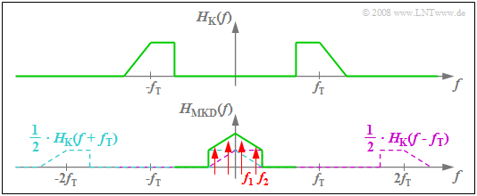
$\text{Example 3:}$ The diagram illustrates the above calculation rule for the resulting system function..
- From the asymmetric band-pass $H_{\rm K}(f)$ – related to the carrier frequency $f_{\rm T}$ – we get the symmetric function $H_{\rm MKD}(f)$ in the low-frequency range $($around $f = 0)$.
- If the source signal consists of two frequency components – indicated in the graph by the red marker arrows – the spectral line at $f_2$ is more attenuated than the frequency $f_1$ ⇒ linear attenuation distortions arise.
- The fact that $H_{\rm MKD}(f)$ also includes components around $±2f_{\rm T}$ is not a major concern. These do not affect low-pass considerations.
Influence of noise interference
Now we wish to clarify the extent to which the transmission quality is affected by a stochastic interference or a noise signal $n(t)$. We will be assuming the following scenario, which has already been presented on the Investigations at the AWGN channel page.
In particular, we make the following assumptions:
- Only double-sideband amplitude modulation with modulation depth $m$ and an ideal synchronous demodulator without phase and frequency offsets are considered.
- According to the extended AWGN channel model, where $α_{\rm K}$ is a frequency-independent transmission factor of the channel and the interference signal $n(t)$ models white noise with two-sided noise power density $N_0/2$, the following holds for the received signal:
- $$r(t) = \alpha_{\rm K} \cdot s(t) + n(t) \hspace{0.05cm}.$$
- Representing a source signal $q(t)$ of bandwidth $B_{\rm NF}$ , a cosine-shaped message signal of frequency $B_{\rm NF}$ is assumed here:
- $$q(t) = A_{\rm N} \cdot \cos(2 \pi \cdot B_{\rm NF} \cdot t ) \hspace{0.05cm}.$$
With these assumptions, the sink signal is $v(t) = \alpha_{\rm K} \cdot q(t) + \varepsilon(t) \hspace{0.05cm}$, where the cause of the stochastic component $ε(t)$ at the output is the band-pass noise $n(t)$ at the input of the synchronous demodulator.
$\text{Definition:}$
- The signal-to-noise power ratio at the sink is used as a quantitative measure of transmission quality, and is expressed here in powers of $q(t)$ and $ε(t)$:
- $$\rho_v = \frac{\alpha_{\rm K}^2 \cdot P_q}{P_\varepsilon} \hspace{0.05cm}.$$
- In the following, we will refer to this ratio as the sink SNR $ρ_v$ and the logarithmic representation $10 · \lg ρ_v$ as the sink SNR in dB.
Calculating the noise power
We first calculate the power $P_ε$ of the error signal $ε(t)$, which we refer to as the "noise power" for simplicity.
The error signal $ε(t)$ at the output is obtained from the noise signal $n(t)$ at the input by
- multiplying by $z_{\rm E}(t) = 2 · \cos(ω_{\rm T} · t + \mathbf{ϕ_{\rm T} })$ and
- a subsequent (ideal) low-pass filtering to the low-frequency range $\pm B_{\rm NF}$.
For the power-spectral density $\rm (PSD)$ ${\it Φ_ε}'(f)$ without considering the low-pass filter, it holds with ${\it Φ}_n(f) = N_0/2$:
- $${\it \Phi}_\varepsilon \hspace{-0.10cm} '(f) = {\it \Phi}_n (f) \star {\it \Phi}_{z {\rm E}}(f) \hspace{0.05cm}.$$
In the books "Signal Representation" and "Theory of Stochastic Signals”, it was shown that
- the spectrum of a cosine signal $x(t) = A · \cos(2πf_{\rm T}t)$ is given by:
- $$X(f) = \frac{A}{2}\cdot \delta(f + f_{\rm T}) + \frac{A}{2}\cdot \delta(f - f_{\rm T}) \hspace{0.05cm}, $$
- whereas for the power-spectral density of a cosine signal $x(t) = A · \cos(2πf_{\rm T}t)$:
- $$ {\it \Phi}_x (f) = \frac{A^2}{4}\cdot \delta(f + f_{\rm T}) + \frac{A^2}{4}\cdot \delta(f - f_{\rm T}) \hspace{0.05cm}.$$
Applied to the receiver-side carrier signal $z_{\rm E}(t)$, with $A = 2$:
- $${\it \Phi}_{z {\rm E}}(f)= \delta(f + f_{\rm T}) + \delta(f - f_{\rm T}) \hspace{0.05cm},$$
and this is independent of phase (since all phase relationships are lost in the power-spectral density).
$\text{Example 4:}$ Considering that ${\it Φ}_n(f)$ is constant for all frequencies ⇒ "White Noise", we get:
- $${\it \Phi}_\varepsilon \hspace{-0.10cm} '(f) = {\it \Phi}_n (f + f_{\rm T}) + {\it \Phi}_n (f - f_{\rm T}) = 2 {\it \Phi}_n (f) = N_0 \hspace{0.05cm}.$$
- The power-spectral density $\rm (PSD)$ after the low-pass filter is exactly as large for $ \vert f \vert < B_{\rm NF}$ and zero beyond this range.
- $${\it \Phi}_\varepsilon (f) = \left\{ \begin{array}{c} N_0 \\ 0 \\ \end{array} \right.\quad \begin{array}{*{10}c} {\rm{for} }\\ \\ \end{array}\begin{array}{*{20}c} \vert f \vert < B_{\rm NF} \hspace{0.05cm}, \\ {\rm otherwise} \hspace{0.05cm}. \\ \end{array}$$
- By integration, we obtain the power $P_ε = 2N_0 · B_{\rm NF}$. Thus, with this intermediate result, the sinking SNR can be given as:
- $$\rho_v = \frac{\alpha_{\rm K}^2 \cdot P_q}{P_\varepsilon} = \frac{\alpha_{\rm K}^2 \cdot P_q}{N_0 \cdot B_{\rm NF} } \hspace{0.05cm}.$$
In the next section, we still establish the relationship between the power $P_q$ of the source signal and the transmission power $P_{\rm S}$.
Relationship between the powers from source signal and transmitted signal
To characterise the relationship between the sink–SNR $\rho_v$ and the transmission power $P_{\rm S}$, we first need the relationships between
- source signal $q(t)$ ⇒ power $P_q$, and
- transmitted signal $s(t)$ ⇒ transmission power $P_{\rm S}$.
$\text{Anticipated result:}$ In the case of »DSB–AM with carrier« the following holds true for a modulation depth $m$:
- $$P_{\rm S} = { P_q}/{2} \cdot \hspace{0.05cm} \left( 1 + {2}/{m^2}\right)\hspace{0.05cm}.$$
- Note that this equation is only applicable when $q(t)$ describes a harmonic oscillation.
- The »DSB–AM without carrier« is included in the equation as a special case for $m \to \infty$.
$\text{Proof:}$ Cosine oscillations are assumed in each case, i.e. the following equations:
- $$q(t) = A_{\rm N} \cdot \cos(\omega_{\rm N} \cdot t ) \hspace{0.05cm},$$
- $$s(t) = \big[ q(t) + A_{\rm T}\big] \cdot \cos(\omega_{\rm T} \cdot t ) = A_{\rm T} \cdot \cos(\omega_{\rm T} \cdot t ) + {A_{\rm N} }/{2}\cdot \cos\big [(\omega_{\rm T}+ \omega_{\rm N}) \cdot t \big] + {A_{\rm N} }/{2}\cdot \cos\big[(\omega_{\rm T}- \omega_{\rm N}) \cdot t \big]\hspace{0.05cm}.$$
- The power of the source signal, in relation to a resistance of $1 \ \rm Ω$, with the period $T_{\rm N}$, is:
- $$P_{q} = \frac{1}{T_{\rm N} }\cdot\int_{0}^{ T_{\rm N} } {q^2(t)}\hspace{0.1cm}{\rm d}t = \frac{A_{\rm N}^2}{T_{\rm N} }\cdot\int_{0}^{T_{\rm N} } {\cos^2(2 \pi\cdot{t}/{T_{\rm N} })}\hspace{0.1cm}{\rm d}t = \frac{A_{\rm N}^2}{2}\hspace{0.05cm}.$$
- Accordingly, for the power of the transmitted signal, one obtains:
- $$P_{\rm S} = \frac{A_{\rm T}^2}{2} + \frac{(A_{\rm N}/2)^2}{2} + \frac{(A_{\rm N}/2)^2}{2} = \frac{A_{\rm T}^2}{2} + \frac{A_{\rm N}^2}{4} \hspace{0.3cm}\Rightarrow \hspace{0.3cm} P_{\rm S} = {1}/{2} \cdot \left( P_q + A_{\rm T}^2 \right) \hspace{0.05cm}.$$
- This equation is valid for both »DSB–AM without carrier« $(A_{\rm T} = 0)$ and »DSB–AM with carrier«. Since $q(t)$ was assumed to be a harmonic oscillation, »DSB–AM without carrier« given a modulation depth $m = A_{\rm N}/A_{\rm T}$, this can also be written as:
- $$P_{\rm S} = {A_{\rm N}^2}/{4} \cdot \left( 1 +{2A_{\rm T}^2}/{A_{\rm N}^2} \right)= P_q/2 \cdot \left( 1 +{2}/{m^2} \right)\hspace{0.05cm}.\hspace{5.4cm}{\rm q.e.d.}$$
Sink SNR and the performance parameter
With the results of the last three sections, the sink SNR of double-sideband amplitude modulation can be written as:
- $$\rho_v = \frac{\alpha_{\rm K}^2 \cdot P_q}{P_\varepsilon} = \frac{\alpha_{\rm K}^2 \cdot P_{\rm S} }{N_0 \cdot B_{\rm NF} } \cdot \frac{1}{1 + {2}/{m^2} } \hspace{0.05cm}.$$
The following is a detailed discussion of this equation. Already in the chapter Investigations at the AWGN channel it was justified why it makes sense to state the sink SNR $ρ_v$ as a function of the performance parameter $ξ$ named below:
- $$\xi = \frac{\alpha_{\rm K}^2 \cdot P_{\rm S}}{N_0 \cdot B_{\rm NF}} \hspace{0.5cm}\Rightarrow \hspace{0.5cm} \rho_v = \frac{\xi}{1 + {2}/{m^2}} \hspace{0.05cm}.$$
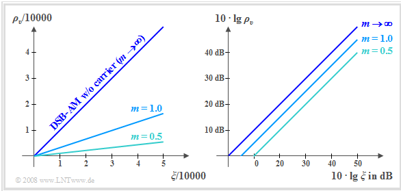
The two graphs show the corresponding curves
- linear on the left,
- double-logarithmic on the right.
The curves are to be interpreted as follows:
- For the system variant »DSB–AM without carrier« with $m → ∞$ the above equation yields the simple relationship $ρ_v = ξ$. This gives the bisector of the angle for both the linear and double logarithmic plots.
- A greater transmission power $P_{\rm S}$ leads to a better sink SNR, as does a larger transmission factor $α_{\rm K}$ (⇒ lower attenuation). However, $10 · \lg ρ_v$ is also increased by a smaller noise power density $N_0$ and a smaller bandwidth $B_{\rm NF}$, other things being equal.
- For »DSB–AM with carrier« with a modulation depth $m$:
- $$\rho_v = \xi \cdot \frac{1}{1 + {2}/{m^2}}\hspace{0.3cm}\Rightarrow \hspace{0.3cm} 10 \cdot {\rm lg }\hspace{0.1cm}\rho_v = 10 \cdot {\rm lg }\hspace{0.1cm}\xi - 10 \cdot {\rm lg }\hspace{0.1cm} \left({1 + {2}/{m^2}}\right)\hspace{0.05cm}.$$
- In the double logarithmic representation (see right graph), this leads to a downward parallel shift of the curves,
e.g. at $m = 1$ by $4.77$ dB and at $m = 0.5$ by $9.54$ dB. - All statements are valid under the assumption of an ideal synchronous demodulator. In this case, the »DSB–AM with carrier« method actually makes no sense. The added carrier would only lead to an unnecessarily large transmit power and could not be used for demodulation.
- The curves are valid for perfect frequency and phase synchronization. However, in order to be able to determine the parameters $f_{\rm T}$ and $\mathbf{ϕ_{\rm T} }$ from the received signal $r(t)$ with less effort, a small carrier component in the transmitted signal makes sense.
- When $m = 3$, it is only an insignifican deterioration of less than one dB compared to »DSB–AM without carrier«.
Exercises for the Chapter
Exercise 2.4: Frequency and Phase Offset
Exercise 2.4Z: Low-pass influence with Synchronous Demodulation
Exercise 2.5: DSB-AM via a Gaussian Channel
Exercise 2.5Z: Linear Distortions with DSB-AM
Exercise 2.6: Free Space Attenuation
Exercise 2.6Z: Signal-to-Noise-Ratio (SNR)
