Difference between revisions of "Examples of Communication Systems/Radio Interface"
| Line 269: | Line 269: | ||
==Radio Subsystem Link Control== | ==Radio Subsystem Link Control== | ||
<br> | <br> | ||
| − | + | Another function of the radio interface is the control of the radio link. Thus, the so-called ''Radio Subsystem Link Control'' performs the following tasks: | |
| + | It is responsible for the measurement of the reception quality. During an established traffic or signaling connection, the channel measurement of the mobile station is performed at regular intervals with regard to received field strength and bit error rate ⇒ '''Quality Monitoring'''. These values are transmitted in a measurement report to the base station via the signaling channel SACCH and used by it for power control and handover. | ||
| − | + | The ''Power Control'' is necessary to ensure that all mobile stations only radiate with the minimum required power. The transmit power can be adaptively controlled in steps of $2 \ \rm dBm$ between $43 \ \rm dBm$ $\text{(level 0:}$ $20\ \rm W$) and $13 \ \rm dBm$ $\text{(level 15:}$ $20\ \rm mW$) . Base station transmit power is also adjusted in steps of $2 \rm dBm$ to achieve optimum network capacity. An exception is the BCCH carrier with constant transmit power to allow mobile stations to make comparative measurements of neighboring BCCH carriers. | |
| − | |||
| − | |||
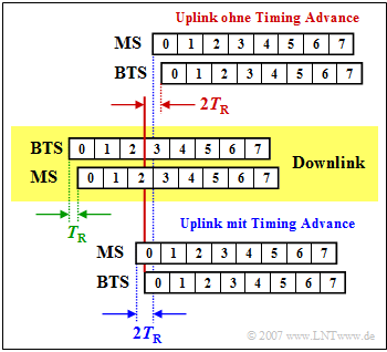
[[File:P_ID3110__Bei_T_3_2_S11_v2.png|right|frame|Adaptive Frame Alignment]] | [[File:P_ID3110__Bei_T_3_2_S11_v2.png|right|frame|Adaptive Frame Alignment]] | ||
| − | + | The '''Adaptive Frame Alignment''' - i.e. adaptive frame synchronization - is used to avoid collisions between uplink and downlink data to be transmitted or received by the mobile station offset by three time slots. This is shown in the adjacent graphic. | |
| − | + | The downlink is shown in the middle area with a yellow background, where the data arrives at the mobile station (MS) later than it was sent by the ''Base Transceiver Station'' (BTS) by the time $T_{\rm R}$ (''Round Trip Delay Time'') (green marking). | |
| − | + | In the upper area, the uplink is shown without ''Timing Advance'' . | |
| − | * | + | *The MS starts sending exactly three time slots after reception (blue marker). |
| − | * | + | *Due to the delays in the downlink and uplink, the time slot $0$ does not reach the BTS at the time $3T_{\rm Z}$ as required, but by $2T_{\rm Z}$ later (red mark). |
| − | * | + | *With the ''Timing Advance'' uplink (lower sketch) this delay is already compensated by the mobile station by sending the data by the time $T_{\rm A} = 2T_{\rm R}$ earlier and thus they arrive exactly time synchronized at the BTS. |
| − | + | For the ''Timing Advance'' stages $0 - 63$ are available, where each stage corresponds to a bit duration $T_{\rm B}$ . | |
| − | * | + | *The maximum ''Timing Advance'' is thus $\rm 63 - 3.7 \ µ s ≈ 233 \ µs$, giving the maximum allowable runtime in one direction to $T_{\rm R} ≈ 116\ {\rm µ s}$. |
| − | * | + | *From this, the allowed cell radius of GSM (distance between BTS and MS) can be calculated: |
:$$116\ \rm µ s · 3 · 10^8 \ m/s ≈ 35 \ km.$$ | :$$116\ \rm µ s · 3 · 10^8 \ m/s ≈ 35 \ km.$$ | ||
| Line 296: | Line 295: | ||
== Exercises for the chapter== | == Exercises for the chapter== | ||
<br> | <br> | ||
| − | [[Aufgaben:3.3_GSM–Rahmenstruktur|Aufgabe 3.3: GSM–Rahmenstruktur]] | + | [[Aufgaben:3.3_GSM–Rahmenstruktur|"Aufgabe 3.3: GSM–Rahmenstruktur"]] |
| − | [[Aufgaben:3.3Z_GSM_900_und_GSM_1800|Aufgabe 3.3Z: GSM 900 und GSM 1800]] | + | [[Aufgaben:3.3Z_GSM_900_und_GSM_1800|"Aufgabe 3.3Z: GSM 900 und GSM 1800"]] |
| − | [[Aufgaben:3.4_GMSK–Modulation|Aufgabe 3.4: GMSK–Modulation]] | + | [[Aufgaben:3.4_GMSK–Modulation|"Aufgabe 3.4: GMSK–Modulation"]] |
| − | [[Aufgaben:Aufgabe_3.4Z:_FSK_mit_kontinuierlicher_Phase|Aufgabe 3.4Z: FSK mit kontinuierlicher Phase]] | + | [[Aufgaben:Aufgabe_3.4Z:_FSK_mit_kontinuierlicher_Phase|"Aufgabe 3.4Z: FSK mit kontinuierlicher Phase"]] |
==Quellenverzeichnis== | ==Quellenverzeichnis== | ||
Revision as of 20:23, 30 December 2022
Contents
- 1 Logical channels of GSM
- 2 Uplink and downlink parameters
- 3 Realization of FDMA and TDMA
- 4 The different burst types in GSM
- 5 GSM frame structure
- 6 Modulation in GSM systems
- 7 Continuous phase adjustment with FSK
- 8 Minimum Shift Keying (MSK)
- 9 Gaussian Minimum Shift Keying (GMSK)
- 10 Advantages and disadvantages of GMSK
- 11 Radio Subsystem Link Control
- 12 Exercises for the chapter
- 13 Quellenverzeichnis
Logical channels of GSM
The radio interface is crucial for the proper operation of the GSM network and the exchange of information between mobile and base station. This is also called the air interface or physical layer and defines all physical channels of the GSM system as well as their assignment to the logical channels. Furthermore, the radio interface is responsible for other functionalities such as the Radio Subsystem Link Control .
Let's start with the logical channels. These can occupy either an entire physical channel or only a portion of a physical channel and fall into two categories:
- Traffic Channels are used exclusively for the transmission of user data streams such as voice, fax and data. These channels are for both directions – so.
- Mobile Station (MS) ⇔ Base Station Subsystem (BSS)
- designed and can be occupied either by a full rate traffic channel $\text{(13 kbit/s)}$ or by two half rate channels $\text{(5.6 kbit/s each)}$ .
- Control Channels supply all active mobile stations via the radio interface by means of packet-oriented signaling in order to be able to receive messages from the Base Transceiver Station (BTS ) or send messages to the BTS at any time.
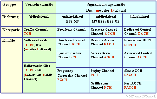
The table lists the logical channels of the GSM.
- These differ from the logical ISDN channels by an additional "m" for "mobile".
- For example, the "Bm channel" is comparable to the B channel of ISDN.
Uplink and downlink parameters
The logical channels are mapped to physical channels which describe all physical aspects of data transport:
- the frequency ranges for uplink (radio link mobile station → base station) and downlink (radio link base station → mobile station),
- the division between Time Division Multiple Access (TDMA) and Frequency Division Multiple Access (FDMA),
- the burst structure, i.e. the occupancy of a TDMA time slot in different applications (user and signaling data, synchronization marks, etc.),
- the modulation method Gaussian Minimum Shift Keying (GMSK), a variant of Continuous Phase - Frequency Shift Keying (CP-FSK) with large bandwidth efficiency.
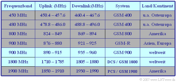
The following table shows the frequency ranges of the standardized GSM systems. To prevent intermodulation interference between the two directions, there is a guard band between the bands for uplink and downlink, the so-called duplex spacing.
$\text{Example 1:}$ With $\text{System GSM 900}$ (in Germany: D-Netz) the uplink starts at $\text{890 MHz}$ and the downlink at $\text{935 MHz}$.
- The duplex spacing is thus $\text{45 MHz}$.
- Both the uplink and the downlink have a bandwidth of $\text{25 MHz}$.
- After subtracting the guard bands at each of the two edges of $\text{100 kHz}$ there remain $\text{24.8 MHz}$, which are divided into $124$ FDMA channels of $\text{200 kHz}$ each.
The $\text{DCS band}$ (E–Netz) in the range around $\text{1800 MHz}$ has a duplex spacing of $\text{95 MHz}$ and a respective bandwidth of $\text{75 MHz}$.
- Taking into account the guard bands, this results in $374$ FDMA channels at $\text{200 kHz}$ each.
Realization of FDMA and TDMA
In the GSM system, two multiple access methods are used in parallel:
- Frequency Division Multiple Access (FDMA); and
- Time division multiple access (Time Division Multiple Access, TDMA).
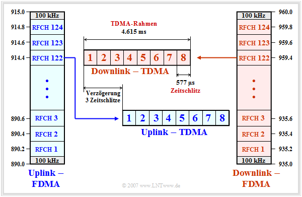
The graphic and the description apply to the $\text{GSM 900}$ system, known in Germany as D-Netz (D network).
Comparable statements apply to the other GSM systems.
We also refer here to the " GSM frame structure" and the "Exercise 3.3".
- In both the uplink and downlink, the transmission of signaling and traffic data occurs in parallel in $124$ frequency channels, designated "RFCH1" to "RFCH124".
- The center frequency of the uplink channel $n$ is at $890 \ {\rm MHz} + n - 0.2 \ {\rm MHz} \ \ ( n = 1$, ... , $124)$. At the upper and lower ends of the $25 \ {\rm MHz}$ band, there are guard bands of $100 \ {\rm kHz}$ each.
- The channel $n$ in the downlink is above the channel $n$ in the uplink at $935 \ {\rm MHz} + n - 0.2 \ {\rm MHz}$ by the duplex spacing of $45 \ {\rm MHz}$. The channels are designated in the same way as those in the uplink.
- Each cell is assigned some frequencies per Cell Allocation (CA). In adjacent cells one uses different frequencies. A subset of the CA is reserved for logical channels. The remaining channels are allocated to a mobile station as Mobile Allocation (MA).
- This is used, for example, for frequency hopping, where the data is sent over different frequency channels. This makes the transmission more stable against channel fluctuations. In most cases, frequency hopping is performed in packets.
- The individual GSM frequency channels are further subdivided by time division multiplexing (TDMA). Each FDMA channel is periodically divided into so-called TDMA frames which in turn each comprise eight time slots.
- The time slots (TDMA channels) are cyclically assigned to the individual subscribers and each contain a so-called burst of $156.25$ bit periods in length. Each GSM user has exactly one of the eight time slots available in each TDMA frame.
- The TDMA frames of the uplink are sent with three time slots delay compared to those of the downlink. This has the advantage that the same hardware of a mobile station can be used for both sending and receiving a message.
- The duration of a time slot is $T_{\rm Z} ≈ 577 \rm µ s$, that of a TDMA frame $4,615 \rm ms$. These values result from the GSM frame structure. In total $26$ TDMA frames are combined into a so-called multiframe of duration $120 \ \rm ms$ :
- $$T_{\rm Z} = \frac{120\,{\rm ms}}{8 \cdot 26} \approx 576.9\,{\rm µ s }\hspace{0.05cm}. $$
The different burst types in GSM
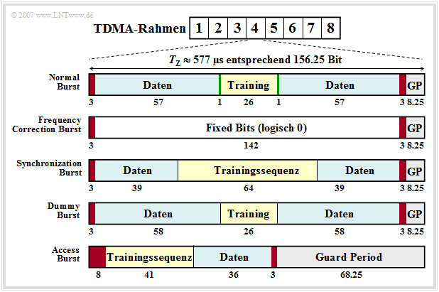
As just shown, a burst contains $156.25$ bits each and has duration $T_{\rm Z} ≈ 577 \rm µ s$.
- From this, the bit duration is calculated to $T_{\rm B} ≈ 3.69 \rm µ s$.
- To avoid overlapping of bursts due to different propagation times between mobile and base station, a Guard Period (GP) is inserted at the end of each burst.
- This guard period is $8.25$ bit durations, so $8.25 - 3.69 \ {\rm µ s} ≈ 30.5 \ {\rm µ s}$.
There are five different types of bursts, as shown in the figure above:
- Normal Burst (NB),
- Frequency Correction Burst (FB),
- Synchronization Burst (SB),
- Dummy Burst (DB),
- Access Burst (AB).
- The Normal Burst is used to transmit data from traffic and signaling channels. The error protection coded user data (blue, two times $57$ bits) together with three tail bits each (red, during this time the transmit power is regulated), two signaling bits (green) and $26$ bits for the training sequence (yellow, required for channel estimation and synchronization) result in a total of $148$ bits. Added to this is the Guard Period of $8.25$ bits (gray).
- The two (green) signaling bits - also called Stealing Flags - indicate whether the burst transports only user data or high-priority signaling information, which is always to be transmitted without delay. The training sequence can be used to estimate the channel, which is a prerequisite for applying an equalizer to reduce pulse interference.
- The Frequency Correction Burst' is used to frequency synchronize a mobile station. All bits except the tail bits and the guard period are here set to logical "$0$". The repeated broadcast of such a burst on the Frequency Correction Channel (FCCH) corresponds to an unmodulated carrier signal with frequency $f_{\rm T} + Δf_{\rm A}$ (carrier frequency + frequency deviation) (Günter: Frequenzhub -> Frequency deviation?). This value results from the fact that the modulation method "Gaussian Minimum Shift Keying" is a FSK special case.
- The Synchronization Burst'' is used to transmit information that helps a mobile station synchronize in time with the BTS. Besides a long midamble of $64$ bits, the Synchronization Burst contains the TDMA frame number and the Base Transceiver Station Identity Code (BSIC). When such a burst is repeatedly broadcast, it is referred to as the Synchronization Channel (SCH).
- The Dummy Burst (DB) is transmitted by each Base Transceiver Station (BTS) on a frequency specially allocated to it (Cell Allocation) when there are no other bursts to be transmitted. This ensures that a mobile station can always take power measurements.
- The Access Burst' is used for random multiple access on the Random Access Channel (RACH). To keep the probability of collisions on the RACH low, the Access Burst has a substantially longer Guard Period of $68.25$ bit durations than the other bursts.
GSM frame structure
The GSM frame structure is used to map logical channels to physical channels. Here a distinction is made between
- the mapping in frequency, based on Cell Allocation (CA), Mobile Allocation (MA), the TDMA frame number (FN) and the rules for the (optional) Frequency Hopping,
- the mapping in time, where the TDMA frames are grouped into multiframes, superframes and hyperframes, each with eight time slots for transmitting the bursts.
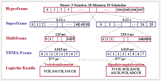
According to this picture, the following statements are valid:
- Multiframes are used for mapping logical channels to physical channels. Two types can be distinguished here, those with $26$ TDMA frames and a cycle duration of $120 \ \rm ms$ and those with $51$ TDMA frames and a duration of $235.4 \ \rm ms$.
- The bursts of the traffic channels (TCH) and the associated control channels (SACCH, FACCH) are transmitted in $26$ successive TDMA frames each. Only one time slot per TDMA frame is always considered for the respective multiframe.
- Of the gross data rate per user $\text{(approx. 33.9 kbit/s)}$ are $\text{9.2 kbit/s}$ reserved for synchronization, signaling and Guard Period and $\text{1.9 kbit/s}$ for SACCH and IDLE. The (encoded and encrypted) user data occupy only $\text{22.8 kbit/s}$ for multiframe structure with $26$ frame.
- The multiframe structure with $51$ frames (right half of the picture) is used to multiplex several logical channels onto one physical channel. In 51 consecutive TDMA frames, all data of the signaling channels (except FACCH and SACCH) are transmitted respectively.
- One Superframe consists of $1326$ consecutive TDMA frames $(51$ multiframes with each $26$ TDMA frame or of $26$ multiframes with each $51$ TDMA frame$)$ and lasts approximately $6.12$ seconds.
- A hyperframe groups $2048$ superframes (or $2\hspace{0.08cm}715{\hspace0.08cm}648$ TDMA frames) together and is used with its long cycle duration to synchronize the payload encryption. This is $\text{3 hours, 28 minutes and 53,760 seconds}.$
Modulation in GSM systems
According to the statements of the last pages, $156.25$ bits per time slot $(0.5769 \ \rm ms)$ must be transmitted in one frequency channel. This corresponds to a total bit rate (for eight TDMA users including channel coding, signaling and synchronization information, etc.) of $R_{\rm ges} = 270\hspace{0.08cm}833 \rm bit/s$.
For this bit rate, a bandwidth of $B = 200 \ \rm kHz$ is available for GSM. Therefore, a modulation method with a bandwidth efficiency of at least $β =R_{\rm ges}/B = 1.35$ is required.
In GSM mobile radio, the modulation method Gaussian Minimum Shift Keying' (GMSK) is used. This has already been discussed in detail in the chapter "Nonlinear Digital Modulation" of the book "Modulation Methods". Here follows a brief, bullet-point description:
- GMSK is a modified form of Frequency Shift Keying' (FSK). This results from driving a "Frequency Modulator" with a binary bipolar rectangular input signal.
- Such an FSK signal $s(t)$ contains within each symbol duration $T$ only a single instantaneous frequency at a time $f_{\rm A}(t) = \rm const. $ If the (normalized) input signal is equal $+1$, then $f_{\rm A}(t)$ is equal to the sum of the carrier frequency $f_{\rm T}$ and the frequency deviation $Δf_{\rm A}$. Correspondingly, for the amplitude value $-1$: $f_{\rm A}(t) = f_{\rm T} - Δf_{\rm A}$.
- To allow easy demodulation, the two signals with frequencies $f_{\rm T} ± Δf$ should be orthogonal to each other within the symbol duration $T$ . Consequently, it must hold:
- $$\int^{T} _{0} \cos \big(2 \pi t \cdot (f_{\rm T}+ \Delta f_{\rm A} )\big)\cdot \cos \big(2 \pi t \cdot (f_{\rm T}- \Delta f_{\rm A} )\big)\,{\rm d}t= 0\hspace{0.05cm}. $$
- This results in the requirement for the frequency deviation :
- $$\Delta f_{\rm A} = \frac{k}{4 \cdot T}\hspace{0.2cm}{\rm with}\hspace{0.2cm}k = 1, 2, 3, \text{...}$$
- Since in FSK systems the modulation index' is defined to $h = 2 - Δf_{\rm A} - T$ is defined, it follows $h = k/2$. Thus, the smallest value satisfying the orthogonality conditions is $h_{\rm min} = 0.5$.
- An FSK system with $h = 0.5$ or $Δf_{\rm A}$ = ${1}/{4T}$ is called "Minimum Shift Keying" - MSK for short. This is used in all GSM systems, because a larger modulation index than $h = 0.5$ would require a significantly larger bandwidth.
- A very narrow spectrum results, however, only if phase jumps are avoided at the symbol boundaries by phase value matching. MSK thus belongs to the Continuous Phase Frequency Shift Keying techniques (CP-FSK, see next page).
- An additional low-pass filter with Gaussian characteristics is inserted before the frequency modulator, further reducing the GSM bandwidth. This type of modulation is called "Gaussian Minimum Shift Keying" ('GMSK).
Continuous phase adjustment with FSK
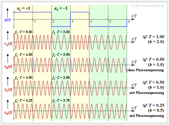
Starting from the rectangular wave signal $q(t)$ and the carrier frequency $f_{\rm T} = 4/T$ we consider the FSK signals $s_{\rm A}(t)$, ... , $s_{\rm D}(t)$ at different frequency deviation $Δf_{\rm A}$ ⇒ modulation index $h = 2 - Δf_{\rm A} - T$.
Regarding the signal characteristics it is to be noted (we also refer to the interactive applet "Frequency Shift Keying & Continuous Phase Modulation"):
- The signal $s_{\rm A}(t)$ results in $Δf_{\rm A} = 1/T$ ⇒ modulation index $h = 2$. One can see the higher frequency $f_1 = 5/T$ $($for $a_ν = +1)$ compared to the frequency $f_2 = 3/T$ $($for $a_ν = -1)$.
- With $Δf_{\rm A} = 0.5/T$ $($signal $s_{\rm {\rm B}}(t)$, $h = 1)$ $f_1 = 4.5/T$ and $f_2 = 3.5/T$ holds. At each symbol boundary, a phase jump of $π$ occurs if no phase adjustment is made as for the signal $s_{\rm C}(t)$ .
- When $s_{\rm C}(t)$ is applied in the range $0$ ... $T$ the coefficient $a_1 = +1$ is represented by $\cos(2π-f_1-t)$ while the also positive coefficient $a_2 = +1$ in the range $T$ ... $2T$ leads to the signal $-\cos(2π-f_1\hspace{0.01cm}-\hspace{0.01cm}(t-T))$ . Phase jumps are thus avoided by this adjustment.
- The signal $s_{\rm D}(t)$ describes the MSK signal $($frequency deviation $Δf_{\rm A} = 0.25/T$ ⇒ modulation index $h = 0.5)$, also with phase adjustment. Here, at each symbol boundary - depending on the previous symbols - four different initial phases are possible.
- For $\rm GSM \ 900$ the carrier frequency is $f_{\rm T} = 900\ \rm MHz$ and the symbol duration is $T ≈ 3.7 \ \rm µ s$. With the modulation index $h = 0.5$ this gives $Δf_{\rm A} ≈ 68 \ \rm kHz$. The two frequencies $f_1 = 900.068\ \rm MHz$ and $f_2 = 899.932\ \rm MHz$ are thus very close to each other.
Minimum Shift Keying (MSK)
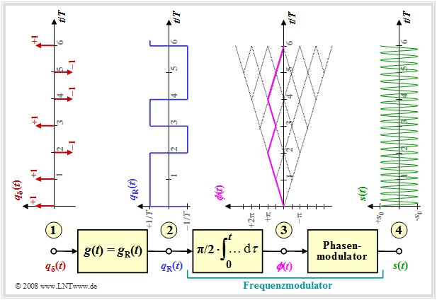
The diagram shows the model for generating an MSK modulation and typical signal characteristics.
One recognizes
- at the point (1)' the digital source signal consisting of a sequence of dirac pulses at distance $T$ weighted by the amplitude coefficients $a_ν ∈ \{-1, +1\}$:
- $$q_\delta(t) = \sum_{\nu = - \infty}^{+\infty}a_{ \nu} \cdot \delta (t - \nu \cdot T)\hspace{0.05cm}; $$
- at the point (2)' the rectangular wave signal $q_{\rm R}(t)$ after convolution with the rectangularwave pulse $g(t)$ the duration $T$ and the height $1/T$ (the amplitude was chosen this way for compatibility with later pages):
- $$q_{\rm R}(t) = \sum_{\nu = - \infty}^{+\infty}a_{ \nu} \cdot g (t - \nu \cdot T)\hspace{0.05cm}; $$
- the frequency modulator, which can be realized as an integrator and downstream phase modulator according to the description in chapter "Signal characteristics in FM" . For the signal at the point (3)' then holds:
- $$\phi(t) = \frac{\pi}{2}\cdot \int_{0}^{t} q_{\rm R}(\tau)\hspace{0.1cm} {\rm d}\tau \hspace{0.05cm}.$$
The phase values at symbol duration $T$ are multiples of $π/2 \ (90^\circ)$, taking into account the modulation index $h = 0.5$ valid for MSK. The phase response is linear. From this, at the point (4)' of the block diagram, the MSK signal is given by
- $$s(t) = s_0 \cdot \cos \big(2 \pi f_{\rm T} \hspace{0.05cm}t + \phi(t)\big) = s_0 \cdot \cos \big(2 \pi \cdot t \cdot (f_{\rm T}+a_{ \nu} \cdot {\rm \Delta}f_{\rm A} )\big) \hspace{0.05cm}.$$
The realization of Minimum Shift Keying (MSK) by a special variant of Offset-QPSK is illustrated by the interactive applet "QPSK and Offset-QPSK" .
Gaussian Minimum Shift Keying (GMSK)
One advantage of MSK over other modulation types is the lower bandwidth requirement. Minor modifications to the "Gaussian Minimum Shift Keying" - abbreviated GMSK - result in a narrower spectrum.
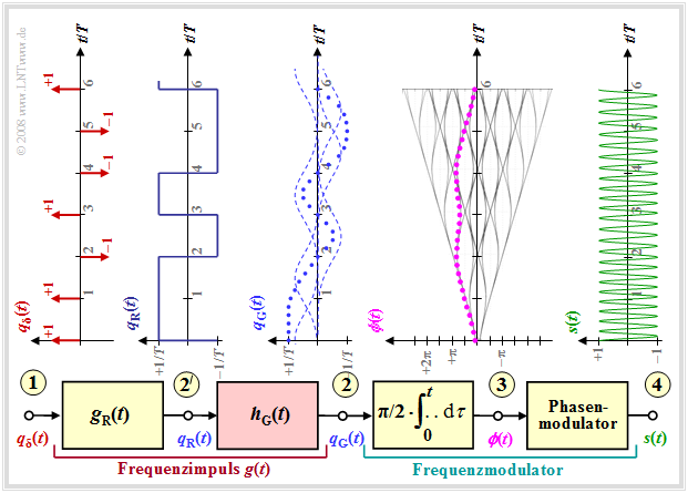
One can see from the block diagram the following differences to the MSK (we refer to the interactive applet "Frequency Shift Keying & Continuous Phase Modulation"):
- The frequency pulse $g(t)$ is now no longer rectangular like the pulse $g_{\rm R}(t)$, but has flatter edges. Consequently, there is also a smoother phase progression at the point (3)' than with the MSK method (see last page), where $ϕ(t)$ symbolically rises or falls linearly.
- These smoother phase transitions in GMSK are achieved by a Gaussian low-pass filter with the frequency response or impulse response
- $$H_{\rm G}(f) = {\rm e}^{-\pi \hspace{0.05cm} \cdot \hspace{0.05cm} \big({f}/(2 \hspace{0.05cm} \cdot \hspace{0.05cm} f_{\rm G})\big)^2} \hspace{0.2cm}\bullet\!\!-\!\!\!-\!\!\!-\!\!\circ\, \hspace{0.2cm} h_{\rm G}(t) = 2 f_{\rm G} \cdot {\rm e}^{-\pi\hspace{0.05cm} \cdot \hspace{0.05cm} (2 \hspace{0.05cm} \cdot \hspace{0.05cm} f_{\rm G}\hspace{0.05cm} \cdot \hspace{0.05cm} t)^2}\hspace{0.05cm}.$$
- For GSM, the 3dB cutoff frequency is set to $f_{\rm 3dB} = 0.3/T$ . Thus, as shown in exercise "Exercise 3.4" , the system theoretic cutoff frequency is:
- $$f_{\rm G} ≈ 1.5 - f_{\rm 3dB} = 0.45/T.$$
- The resulting frequency impulse $g(t)$ at the point (2)' of the block diagram results from the convolution of the rectangular wave impulse $g_{\rm R}(t)$ with the impulse response $h_{\rm G}(t)$ of the Gaussian low pass to
- $$g(t) = g_{\rm R}(t) \star h_{\rm G}(t)\hspace{0.05cm}. $$
- The GMSK-modulated signal $s(t)$ now no longer exhibits a constant frequency section by section (per symbol duration).
However, it is difficult to see this difference from MSK from the signal waveform at point (4) of the block diagram.
Advantages and disadvantages of GMSK
Here, the main features of the modulation method Gaussian Minimum Shift Keying are summarized.
$\text{Conclusion:}$ The main advantage of GMSK is its very low bandwidth requirements.
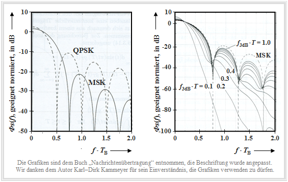
The following graphic was taken from the book [Kam04][1] .
- The left graph shows the log power density spectrum $10 - \text{lg} \ {\it Φ}_s(f)/{\it Φ}_0$ of the method Minimum Shift Keying (MSK) compared to Quaternary Phase Shift Keying (QPSK), where ${\it Φ}_0$ "suitable" was chosen.
- On the abscissa is plotted the normalized frequency $f - T_{\rm B}$ . For MSK, the bit duration $T_{\rm B}$ is equal to the symbol duration $T$, while for QPSK $T_{\rm B} = T/2$ holds.
- In the right diagram, which refers exclusively to (G)MSK , the abscissa could also be labeled $f - T$ .
One recognizes from the left representation:
- The first zero in the power spectral density (PSD) occurs at the normalized abscissa value $f - T_{\rm B} = 0.5$ for QPSK (dashed curve), but for MSK only at $f - T_{\rm B} = 0.75$.
- In the further course, however, MSK results in a much faster PSD decay than the asymptotic $f^{-2}$ decay for QPSK.
- Note that for MSK a cosine pulse is used for spectral shaping and for QPSK a rectangular wave pulse.
The right plot shows the influence of Gaussian pulse shaping in GMSK on the power spectral density ${\it Φ}_s(f)$, where the normalized 3dB cutoff frequency is used as parameter.
- The smaller $f_{\rm 3\ dB}$ is, the more narrowband is the power density spectrum. In the GSM standard $f_{\rm 3\ dB} - T$ = 0.3 has been specified. With this value, the bandwidth is already decisively reduced, resulting in lower adjacent channel interference .
- On the other hand, with this cutoff frequency the impulse interferences already have a serious effect. The eye opening is smaller than $50\%$ and a suitable equalization has to be provided.
Furthermore, it should be noted:
- Binary FSK - even with continuous phase matching - generally represents a nonlinear modulation process. Therefore, coherent demodulation is actually not possible.
- An exception is the MSK as a special case for the modulation index $h = 0.5$, which can be realized linearly as Offset-QPSK and thus can also be demodulated coherently.
- Without taking pulse interference into account, the bit error probability is as follows.
- $$p_{\rm B} = {\rm Q} \left(\sqrt{{E_{\rm B}}/{N_0}}\hspace{0.09cm}\right) = {1}/{2}\cdot{\rm erfc} \left(\sqrt{{E_{\rm B}}/{2N_0}}\hspace{0.09cm}\right) \hspace{0.05cm}.$$
- Compared to the QPSK, there is a degradation of $3\ \rm dB$. The interactive applet "Complementary Gaussian Error Functions" provides the numerical values of the functions used here ${\rm Q}(x)$ respectively. $1/2 \cdot {\rm erfc}(x)$.
- An advantage of GMSK over QPSK is that a constant envelope is obtained despite the spectral shaping of the fundamental pulse. Therefore, nonlinearities on the channel do not play as large a role as in other modulation schemes. This allows the use of simple and inexpensive power amplifiers, lower power consumption and thus also longer operating times of battery-powered devices.
Radio Subsystem Link Control
Another function of the radio interface is the control of the radio link. Thus, the so-called Radio Subsystem Link Control performs the following tasks:
It is responsible for the measurement of the reception quality. During an established traffic or signaling connection, the channel measurement of the mobile station is performed at regular intervals with regard to received field strength and bit error rate ⇒ Quality Monitoring. These values are transmitted in a measurement report to the base station via the signaling channel SACCH and used by it for power control and handover.
The Power Control is necessary to ensure that all mobile stations only radiate with the minimum required power. The transmit power can be adaptively controlled in steps of $2 \ \rm dBm$ between $43 \ \rm dBm$ $\text{(level 0:}$ $20\ \rm W$) and $13 \ \rm dBm$ $\text{(level 15:}$ $20\ \rm mW$) . Base station transmit power is also adjusted in steps of $2 \rm dBm$ to achieve optimum network capacity. An exception is the BCCH carrier with constant transmit power to allow mobile stations to make comparative measurements of neighboring BCCH carriers.
The Adaptive Frame Alignment - i.e. adaptive frame synchronization - is used to avoid collisions between uplink and downlink data to be transmitted or received by the mobile station offset by three time slots. This is shown in the adjacent graphic.
The downlink is shown in the middle area with a yellow background, where the data arrives at the mobile station (MS) later than it was sent by the Base Transceiver Station (BTS) by the time $T_{\rm R}$ (Round Trip Delay Time) (green marking).
In the upper area, the uplink is shown without Timing Advance .
- The MS starts sending exactly three time slots after reception (blue marker).
- Due to the delays in the downlink and uplink, the time slot $0$ does not reach the BTS at the time $3T_{\rm Z}$ as required, but by $2T_{\rm Z}$ later (red mark).
- With the Timing Advance uplink (lower sketch) this delay is already compensated by the mobile station by sending the data by the time $T_{\rm A} = 2T_{\rm R}$ earlier and thus they arrive exactly time synchronized at the BTS.
For the Timing Advance stages $0 - 63$ are available, where each stage corresponds to a bit duration $T_{\rm B}$ .
- The maximum Timing Advance is thus $\rm 63 - 3.7 \ µ s ≈ 233 \ µs$, giving the maximum allowable runtime in one direction to $T_{\rm R} ≈ 116\ {\rm µ s}$.
- From this, the allowed cell radius of GSM (distance between BTS and MS) can be calculated:
- $$116\ \rm µ s · 3 · 10^8 \ m/s ≈ 35 \ km.$$
Exercises for the chapter
"Aufgabe 3.3: GSM–Rahmenstruktur"
"Aufgabe 3.3Z: GSM 900 und GSM 1800"
"Aufgabe 3.4: GMSK–Modulation"
"Aufgabe 3.4Z: FSK mit kontinuierlicher Phase"
Quellenverzeichnis
- ↑ Kammeyer, K.D.: Nachrichtenübertragung. Stuttgart: B.G. Teubner, 4th edition, 2004.
