Contents
- 1 # OVERVIEW OF THE FIRST MAIN CHAPTER #
- 2 The communication system under consideration
- 3 Adapting to the channel frequency response and noise power density
- 4 Channel bundling – frequency division multiplexing
- 5 Analog vs. digital transmission systems
- 6 The historical development of analog modulation methods
- 7 Advantages of digital modulation methods
- 8 Time Division Multiplex methods
- 9 Chapter Exercises
# OVERVIEW OF THE FIRST MAIN CHAPTER #
This book deals with modulation and demodulation, two classical and important methods for Communications Engineering, which already have a very long tradition but are nevertheless constantly developing.
Before analog amplitude and angle modulation are described in detail in the following chapters, along with today's more relevant digital modulation methods, this first chapter introduces the definitions and descriptive variables which are equally valid for all systems.
This chapter deals in detail with:
- the »objectives« of modulation and demodulation,
- the »differences and similarities« betweenanalog and digital modulation techniques,
- the »signal-to-noise power ratio« as a very general quality criterion,
- »linear« and »non-linear distortions« due to modulation/demodulation,
- degradation in the presence of »stochastic interference«, such as » noise«,
- a »unified model« for describing of amplitude and angle modulation,
- descriptions using the »analytical signal« and the »equivalent low–pass signal«.
The communication system under consideration
Throughout the book "Modulation Methods", we will be base our communication system on the block diagram shown here.
The transmission medium ⇒ physical transmission channel is characterized here by its frequency response $H_{\rm K}(f)$. We will consider:
- Electrical lines (coaxial cable, twisted pair, etc.),
- optical fibres (multimode or single mode),
- radio connections (satellite radio, mobile radio, etc.).
Further considerations:
- Let the source signal $q(t)$ be an analog signal, for example, speech, music or the (analog) output of a camera. Let the corresponding spectrum $Q(f)$ lie in the frequency range $|f| ≤ B_{\rm LF}$ , where the subscript stands for "low frequency".
- The middle block in the above figure also includes interference (interference, crosstalk from other users, impulse interference from power lines, etc.) and noise sources such as thermal and semiconductor noise. These are captured by the interference power density spectrum ${\it Φ}_n(f)$.
- The task of such a message transmission system is to transmit the message or information contained in the source signal $q(t)$ – note the different meaning of these quantities – to the spatially distant sink, with the proviso that the sink signal $v(t)$ differs "as little as possible" from $q(t)$.
- A common problem is that the channel is unsuitable for direct transmission of the source signal $q(t)$ because it contains "unfavourable frequencies". For example, a music signal with frequencies up to about $\text{15 kHz}$ cannot be transmitted directly by radio, since radio propagation is only possible from around $\text{100 kHz}$.
- The only solution here is a signal conversion at the transmitter known as modulation. The output signal of the modulator will be uniformly referred to as the transmission signal $s(t)$ in the following. This is generally at higher frequencies than the source signal $q(t)$.
- Demodulation is the signal reset at the receiver to recover the low frequency sink signal $v(t) ≈ q(t)$ from the high frequency received signal $r(t)$ . With real channels, the desired result $v(t) \equiv q(t)$ is not possible due to the noise $n(t)$ that is always present.
Adapting to the channel frequency response and noise power density
The primary task of modulation (in the sense meant here) is adding a higher frequency carrier signal with carrier frequency $f_{\rm T}$ to shift the source signal to a different frequency position,
- with a more favourable channel frequency response $H_{\rm K}(f)$ and/or
- with a more favourable noise power density spectrum ${\it Φ}_n(f)$.
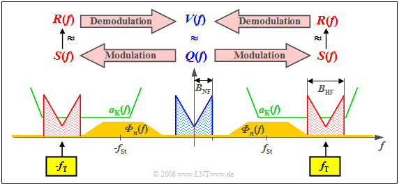
$\text{Example 1:}$ The graph shows the source spectrum $Q(f)\ \bullet\!\!-\!\!\!-\!\!\!-\!\!\circ\,\ q(t)$ with bandwidth $B_{\rm LF}$ (the subscript stands for "low-frequency") in blue.

$\bullet$ Source signal $q(t)\ \circ\!\!-\!\!\!-\!\!\!-\!\!\bullet\,\ Q(f)$, with low-frequency bandwidth $B_{\rm LF}$,
$\bullet$ Transmitted signal $s(t)\ \circ\!\!-\!\!\!-\!\!\!-\!\!\bullet\,\ S(f)$, with high-frequency bandwidth $B_{\rm HF}$,
$\bullet$ Received signal $r(t)\ \circ\!\!-\!\!\!-\!\!\!-\!\!\bullet\,\ R(f)$, with high-frequency bandwidth $B_{\rm HF}$,
$\bullet$ Sink signal $v(t)\ \circ\!\!-\!\!\!-\!\!\!-\!\!\bullet\,\ V(f)$, with low-frequency bandwidth $B_{\rm LF}$,
$\bullet$ Attenuation curve $a_{\rm K}(f) = \ –\ln \ \vert H_{\rm K}(f) \vert $ of channel ⇒ German: "Kanal" ⇒ "K",
$\bullet$ Frequency of the carrier ⇒ German: "Träger" ⇒ "T": $f_{\rm T}$
$\bullet$ Noise power density spectrum ${\it Φ}_n(f)$ with center $f_{\rm N}$.
- The attenuation curve $a_{\rm K}(f) = \ –\ln \ \vert H_{\rm K}(f) \vert $ of the channel is plotted in green, which here shows favourable characteristics with constant low attenuation in a sufficiently large frequency range.
- In dark yellow, you can see the noise power density spectrum ${\it Φ}_n(f)$, which does not disappear throughout the frequency range due to thermal noise and, in our constructed example, takes on particularly large values around the frequency $f_{\rm N}$ due to external interferences.
These boundary conditions make clear:
- One must select the carrier frequency $f_{\rm T}$ approximately as drawn so that $S(f)$ can be transmitted in the best possible way with respect to distortion and interference/noise. This results in a frequency band of sufficient quality with width $B_{\rm HF} = 2 · B_{\rm LF}$.
- This shift of the source signal spectrum $Q(f)$ by the carrier frequency $f_{\rm T}$ to the right – and also by the same distance to the left due to the system-theoretical approach of bilateral frequencies – represents modulation.
- Demodulation, on the other hand, is signal conversion in the opposite direction. Starting from the received spectrum $R(f)$, which differs at least slightly from the transmitted spectrum $S(f)$ due to attenuation and noise, one arrives at the spectral function $V(f) ≈ Q(f)$.
Further reasons for modulation/demodulation are given in the following sections.
Channel bundling – frequency division multiplexing
Another advantage of modulation with a harmonic oscillation as a carrier signal is that a single transmission channel of sufficient bandwidth can be used by several signals simultaneously. One then speaks of
- Frequency Division Multiplexing (FDM)
- or Frequency Division Multiple Access (FDMA).
The diagram illustrates the situation. $K$ message signals are to be transmitted simultaneously via a physical channel of appropriate bandwidth. The subchannels are marked here with $T_1$, ... , $T_K$ . One proceeds as follows:
- One modulates the source signals $q_1(t)$, $q_2(t)$, ... , $q_K(t)$ of users with different carrier frequencies $f_1$, $f_2$, ... , $f_K$.
- One combines the transmission signals $s_1(t)$, $s_2(t)$, ... , $s_K(t)$ to form a total signal 𝑠(𝑡), enabling multiple use of the transmission set-up.
- To demodulate the source signal $q_k(t)$ , one uses the special carrier frequency $f_k$. Subsequent filtering achieves $v_k(t) = q_k(t)$ (but only with negligible noise interference). This process is called channel separation.
$\text{Example 2:}$ Frequency division multiplexing has been used for many decades in analog TV and radio transmission.
- This allows a sufficient number of programs to be accommodated, such as in the UHF band $($frequencies between $\text{470 MHz}$ and $\text{850 MHz)}$ , where more than forty TV programs have a channel spacing of $\text{8 MHz}$.
- However, since around 2004, analog TV transmission in this frequency band has been increasingly displaced by the new digital video standard Digital Video Broadcast – Terrestrial (DVB–T), which also uses FDMA.
$\text{Example 3:}$
- In optical transmission technology, this FDMA method is called wave-length division multiplex (WDM).
- At present (2005), $160$ digital signals at $\text{10 Gbit/s}$ each can be transmitted simultaneously via a single optical fibre ⇒ Total bit rate: $\text{1.6 Tbit/s}$.
Analog vs. digital transmission systems
For the entire book "Modulation Methods", it is assumed that the source signal $q(t)$ and the sink signal $v(t)$ are both analog signals.
- Thus, they can be continuous in both time and value.
- However, this does not yet determine whether the actual transmission is analog or digital.
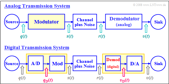
The two block diagrams illustrate the main differences between an analog and a digital message transmission system.
It becomes clear that:
- In analog modulation, the modulating signal $q(t)$ is always an analog signal and thus both continuous in value and in time.
- In contrast, in digital modulation, the modulator's input signal $q_{\rm D}(t)$ is always digital, thus both discrete in value and discrete in time.
- When digitally modulating an analog audio or video signal $q(t)$ , it must first be A/D converted: $q(t) \ \rightarrow \ q_{\rm D}(t)$.
- This is referred to as Pulse-code modulation. This requires the following actions on the transmission side: Sampling – Quantisation – (PCM–)Encoding.
- Functionally, the modulator of the digital system $\rm (Mod)$ does not differ from the modulator of the analog transmission system.
- However, the two demodulators differ in principle: the upper one provides the analog signal $v(t)$, the lower one provides the digital signal $v_{\rm D}(t)$.
- After the digital transmission of an analog signal - such as audio or video - a D/A conversion must therefore still take place.
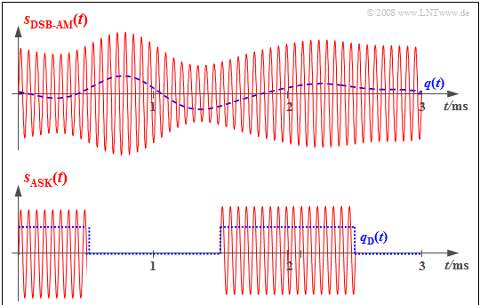
$\text{Example 4:}$ The two graphs show the respective input signals (each in blue dashed lines) and output signals (solid red) of the modulator for an analog and a digital transmission system.
- In the analog transmission system (above), the information about the analog source signal $q(t)$ is directly in the amplitude (envelope) of the modulated signal $s(t)$. This is the analog modulation method Double-sideband amplitude modulation with carrier.
- The bottom graph refers to Amplitude Shift Keying (ASK), the digital variant of amplitude modulation. Here, the modulator input signal $q_{\rm D}(t)$ is digital and derived from the analog source signal $q(t)$ by sampling, quantisation, and PCM encoding.
- The modulated signal $s(t)$ shows that the modulator also has similar functionality in the digital transmission system as in the (above) analog transmission system.
Analog modulation methods currently (2005) still have a certain significance, especially for the distribution of radio and television programs, but are being increasingly displaced by corresponding digital methods in this area. Nevertheless, we will devote more space to analog methods in this book :
- Kapitel 2: Amplitude modulation and AM–Demodulation,
- Kapitel 3: Angle modulation and WM–Demodulation.
$\text{The reasons for this are:}$
- Due to the high costs of retrofitting existing systems or introducing new ones, ever longer runtimes are predicted for analog systems.
- Many components of an analog system are also required for the digital modulation processes, for example the synchronous demodulator used in both variants.
- The typical procedure for investigating aspects of a communications technology can be explained more comprehensively – and often more comprehensibly – for analog systems than for digital systems.
The historical development of analog modulation methods
The following dates represent milestones for the development of analog modulation methods using carrier frequencies:
- the introduction of regular broadcasting service (1923),
- the start of carrier-frequency telephony (1923),
- the introduction of regular television service (1935),
- the first satellite transmission (1945),
- the introduction of NTSC colour television (1953),
- the introduction of PAL colour television (1967).
The following inventions, among others, were necessary for these developments:
- 1861: the electrical transmission of speech ⇒ Philip Reis,
- 1876: the first commercially usable telephone ⇒ Alexander Graham Bell,
- 1884: the development of line scanning ⇒ Paul Julius Gottlieb Nipkow,
- 1887: the discovery of electromagnetic waves ⇒ Heinrich Hertz,
- 1906: the invention of the electron tube ⇒ Robert von Lieben and Lee de Forest,
- 1948: the invention of the transistor ⇒ William Bradford Shockley, Walter Houser Brattain and John Bardeen.
Advantages of digital modulation methods
The advantages of digital modulation methods are numerous:
- The realisation of a digital system can also be done digitally and the circuits can be easily integrated (VLSI – Very Large Scale Integration).
- The transmission quality is usually very good, since (noise) interference is only noticeable if it is greater than a predefined threshold.
- Because signals can be regenerated at regular intervals by so-called regenerators, very large distances can be bridged with sufficiently good transmission quality.
- Data transmission – between server and client, for example – is best done digitally, since every data signal is already digital. Analog signals must first be digitalised before transmission.
- Uniform transmission of voice, image and data signals makes it possible to build a shared, high-performance network for many telecommunications services.
- Simple and highly efficient encryption and data security mechanisms exist for digital signals, which is an important prerequisite for safety-critical applications.
- In a digital system, the advantages of time-division multiplexing – as a possible addition to frequency division multiplexing – can also be exploited, as described below.
- Compact Disc (CD) – digital storage medium; (Philips, 1982),
- Digital European Cordless Telephone (DECT) – cordless telephone (1992),
- Global System for Mobile Communication (GSM) – European mobile communications system (1992),
- Integrated Services Digital Network (ISDN) – digital telephone network (in Europe, 1993),
- Digital Audio Broadcast (DAB) – digital radio broadcasting (2001),
- Digital Video Broadcast (DVB) – digital television (2002),
- Digital Subscriber Line (DSL) – high-speed computer linkage (2002),
- Universal Mobile Telephone System UMTS) – 3rd generation mobile communications (2003),
- Long Term Evolution (LTE) – 4th generation mobile communications (2011).
The numbers in parentheses indicate the year of first use in each case. In most cases, it took more than a decade from invention to standardisation to the development of an operational system.
- Digital modulation methods are summarised in the fourth main Chapter of this book.
- A detailed description (calculation of error probability, aspects of system optimization, etc.) can be found in the book Digital Signal Transmission.
Time Division Multiplex methods
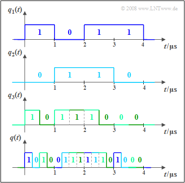
In a digital system, time division multiplexing can be used in addition to frequency division multiplexing to share a transmission channel between several users. The diagram is intended to illustrate the principle using an example:
- The signals $q_1(t), q_2(t)$ and $q_3(t)$ are binary and are fully characterised by amplitude coefficients (0 or 1). A time-discrete signal representation is present $($symbol duration $T = 1\ \rm µ s)$.
- For the bit rates of these first two signals, $R_1 = R_2 = 1/T = \text{1 Mbit/s}$. applies in each case. In contrast, the bit rate of $q_3(t)$ is twice as large, i.e. $R_3 = \text{2 Mbit/s}$.
- The common time-division multiplexed output signal $q(t)$ with the total bit rate $R = R_1 + R_2 + R_3 = \text{4 Mbit/s}$. is shown below. The reference to the input signals is colour coded.
- After transmitting $q(t)$ via the physical channel, the partial signals $v_1(t)$, ... , $v_3(t)$ are separated again at the receiver. This functional unit is called the demultiplexer.
- In practice, multiplexing is usually not done bit by bit, but the nodes are provided with time slots in a fixed grid in which bit frames are transmitted.
Chapter Exercises
Exercise 1.1: Multiplexing in the GSM–System
Exercise 1.1Z: FM Broadcasting


