Contents
System architecture and basic units of GSM
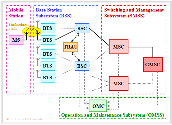
GSM (Global System for Mobile Communication) is a strongly hierarchically structured system of different network components. You can see from the graphic:
- The mobile station (MS) communicates via the radio interface with the nearest Base Transceiver Station (BTS, transmit and receive base station).
- Several such BTS are grouped together area by area and are jointly subordinate to a Base Station Controller (BSC, control station).
- The Base Station Subsystem (BSS) consists of a multitude of BTS and several BSC. In the graphic such a BSS is framed in blue.
- Each BSC is connected to a Mobile Switching Center (MSC, switching computer), whose function is comparable to a switching node in the fixed network.
- Das Gateway Mobile Switching Center (GMSC) is responsible for the connection between the fixed and mobile networks. For example, if a mobile subscriber is called from the fixed network, the GMSC determines the responsible MSC and transfers the call.
- Das Operation and Maintenance Center (OMC) monitors a part of the mobile network. It also takes on organizational tasks such as traffic flow control, charging, security management, etc.
More detailed information on GSM–system architecture and the individual network components can be found in the chapter General Description of GSM of the book "Examples of Message Systems".
Multiple access with GSM
GSM uses two multiple access methods in parallel:
- Frequency Division Multiple Access (FDMA),
- Time Division Multiple Access (TDMA).
The graphic and the following description is valid for the original system "GSM 900" (D–net). For "GSM/DCS 1800" (E–Netz) comparable statements apply.
- In the D–network, a bandwidth of $25\ \rm MHz$ is provided for uplink and downlink respectively $($duplex spacing: $45\ \rm MHz)$. This is called Frequency Division Duplex (FDD). For the E–network, the bandwidth is $75\ \rm MHz$ and the duplex spacing is $95\ \rm MHz$.
.
- Uplink and downlink bands are divided into frequency bands of width $200\ \rm kHz$. Taking into account the protection areas at the respective edges, there are $N_{\rm F} = 124$ (in the D–net) or $N_{\rm F} = 374$ (in the E–net) frequency channels.
- Each cell is assigned a subset of the frequencies ⇒ Cell Allocation. Neighboring cells usually work at different frequencies, for example with the reuse–factor $3$, as in section Cellular Architecture indicated by the colors white, yellow, blue.
.
- The $124$ GSM–Frequency channels are further divided by time division multiplexing (TDMA). Each FDMA–channel is divided into so-called TDMA–frames, which in turn each comprise $N_{\rm T} = 8$ time slots (Time–Slots).
- The slots are periodically assigned to the individual GSM–users and each contain a so-called Burst. Each user has a time slot available in each TDMA–frame. A bundling (maximum six per user) is only possible with GPRS/EDGE.
.
- The TDMA–frames of the uplink are sent delayed by three slots compared to the downlink: Time Division Duplex (TDD). The hardware of the mobile station can thus be used for sending and receiving a message in equal measure.
Data and frame structure for GSM
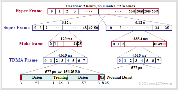
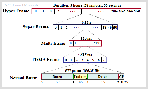
The mapping of logical channels to physical channels is done using the GSM–frame structure. Here we restrict ourselves to traffic channels and to the mapping in time. In this case, each multiframe of duration $120 \ \rm ms$ is divided in $26$ TDMA–frames (two of them for control channels) of duration $4,615\ \rm ms$ . Thus, the duration of a time slot is approximately $T_{\rm Z} = 576.9\ \rm µ s$.
.
You can see from this graphic:
- In each time slot a so-called burst is transmitted, whose duration corresponds to $156.25$ bits. The bit duration is then $T_{\rm B} = 576.9\ \rm µ s/156.25 ≈ 3.692 \ \rm µs$ and for the total bulk data rate:
- \[R_{\rm ges} = {1}/{T_{\rm B}}}= 270,833\,{\rm kbit/s}\hspace{0.05cm}.\]
- The bulk data rate of each user is then $R_{\rm bulk} = 33,854 \ \rm kbit/s$. But since in every normal burst only $2 · 57 = 114$ data bits (highlighted blue in the graphic) are transmitted, it results in the lower net data rate' $R_{\rm net} = 22.8 \ \rm kbit/s$.
- This net data rate also takes the channel coding into account. In the case of a speech signal, for every $20\ \rm kbit/s$–speech frame $456$ bits are transmitted, which results in exactly the rate $22.8 \ \rm kbit/s$ . Without channel coding, the data rate would be only $13 \ \rm kbit/s$.
.
- In addition to the traffic data, a normal burst also contains
- – twice three tailbits (red, during this time the channel is remeasured),
- – two signaling bits (green),
- – the Guard Period (GP) with $8.25$ bit duration $($grey, ca. $30.5 \ \rm µ s)$, and
- – $26$ bit for training sequence (for channel estimation and synchronization),
which increases the data rate from $22.8$ to $33.854 \ \rm kbit/s$ .
Note:
- In GSM, besides the normal burst there are other bursts playing types of bursts (Frequency Correction Burst, Synchronization Burst, Dummy Burst, Access Burst ) a role.
- All these bursts have a uniform length of $156.25$ bit durations. This is discussed in more detail in the Excercise 3.2 .
Modulation method for GSM
With GSM, only a bandwidth of $B = 200 \ \rm kHz$ is available per frequency channel, in which a total data rate (for eight users) of $R_{\rm ges} = 270,833 \ \rm kbit/s$ must be transmitted. A modulation method with a bandwidth efficiency of at least
- \[\beta \ge {R_{\rm ges}}/{B} \approx 1.35 \,\,{\rm bit/s/Hz}.\]
GSM uses the very bandwidth-efficient modulation method checkLink:_Buch_5 ⇒ Gaussian Minimum Shift Keying (GMSK). It should again be expressly mentioned that this modulation procedure, just like the FDMA/TDMA–Multiple Access, is exclusively based on the air interface between the Mobile Station (MS) and the Base Transceiver Station (BTS), which is highlighted in yellow in the System_architecture graphic at the beginning of the chapter.
GMSK has already been described in chapter checkLink:_Buch_5 ⇒ Properties of nonlinear procedures of the book "Modulation Methods". The most important properties are briefly summarized here.
- GMSK is a special form of binary checkLink:_Buch_5 ⇒ Frequency Shift Keying (FSK). A prerequisite for the orthogonality between the two waveforms is that the modulation index $h$ is a multiple of $0.5$ . For integer values of $h$ the demodulation can also be performed non-coherently.
- For GSM you use the smallest possible modulation index $h = 0.5$. A higher value would require a much larger bandwidth. Such an FSK with $h = 0.5$ is also called checkLink:_Buch_5 ⇒ Minimum Shift Keying (MSK). However, a coherent demodulation is then required.
- A very narrow spectrum, however, is only obtained if the phase values at the symbol boundaries are matched to each other, thus avoiding phase jumps, which is given with MSK. Such methods are referred to as checkLink:_Buch_5 ⇒ Continuous Phase Frequency Shift Keying (CP–FSK).
- For GSM, a low-pass filter with Gauss characteristic is inserted before the frequency modulator ⇒ checkLink:_Buch_5 ⇒ Gaussian Minimum Shift Keying (GMSK), which further reduces the bandwidth and improves bandwidth efficiency.
Regarding the topic treated here (coherent or non-coherent demodulation of FSK) we refer to two Exercises in the book "Digital Signal Transmission":
- Excercise 4.16: Binary Frequency Shift Keying,
- Excercise 4.18Z: BER of coherent and non-coherent FSK.
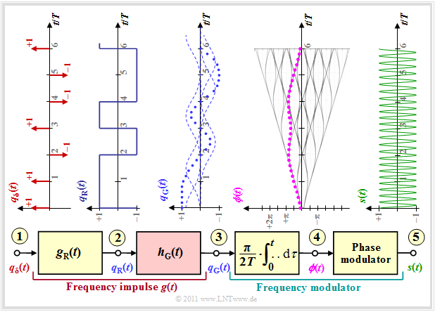
$\text{Example 1:}$ The following graphic is to clarify the previous statements:
- Starting from a dirac-shaped source signal $q_\delta(t)$ at point $(1)$ you pass through a filter with the rectangular impulse response $g_{\rm R}(t)$ to the rectangular signal $q_{\rm R}(t)$ at point $(2)$.
- If the Gaussian low pass with the impulse response $h_{\rm G}(t)$ were to be omitted ⇒ $q_{\rm G}(t) = q_{\rm R}(t)$, a sectionwise linear phase function $\phi(t)$ would result at point $(4)$. All phase values would be multiples of $π/2$ at multiples of the symbol duration $T$ .
- After the phase modulator, a binary FSK–signal $s(t)$ would appear at point $(5)$ with only two frequencies. This signal is at the same time a MSK–signal due to the minimum modulation index $h = 0.5$ in case of orthogonality.
- Through the Gaussian low pass $H_{\rm G}(f)$ with the cutoff frequency $f_{\rm G}= 0.45/T$ (valid for GSM) the frequency pulse $g(t)$ is no longer rectangular but corresponds to the rectangular response of $H_{\rm G}(f)$. According to the Fourier transformation, $g(t) = g_{\rm R}(t) \star h_{\rm G}(t)$ applies.
- Thus, the phase function $\phi(t)$ is no longer linear in sections but the corners are rounded, as can be seen from the phase function at point $(4)$. The violet–dotted curve applies to the data sequence assumed at point $(1)$.
- The signal $s(t)$ at point $(5)$ of the block diagram is the GMSK–signal.
Anmerkung: Das GMSK–Signal beinhaltet deutlich mehr als nur zwei diskrete Frequenzen. Sein Leistungsdichtespektrum fällt sehr schnell ab, siehe Diagramm im Buch „Beispiele von Nachrichtensystemen”. Aus der obigen Zeitdarstellung am Punkt $(5)$ des Blockschaltbildes ist dieser Sachverhalt allerdings nur schwer zu erkennen.
GSM–Erweiterungen
GSM wurde als europäisches Mobilfunksystem für Telefongespräche konzipiert und entwickelt mit der Zusatzoption der Datenübertragung, aber nur mit geringer Datenrate $(9.6 \ \rm kbit/s)$. Die Standardisierung der GSM–Phase 2 ab 1995 beinhaltete aber bereits erste Weiterentwicklungen und einige neue, bereits von ISDN bekannte und von den Nutzern geschätzte Zusatzdienste.
In den Jahren von 1997 bis 2000 wurden neue Datendienste mit höheren Bitraten entwickelt, die man der GSM–Phase 2+ (bzw. GSM–Phase 2.5) zurechnet:
- High–Speed Circuit–Switched Data (HSCSD) bietet bei ausreichend gutem Kanal durch eine höhere Coderate (Punktierung des Faltungscodes) eine leitungsorientierte Übertragung mit $14.4 \ \rm kbit/s$ $($gegenüber $9.6 \ \rm kbit/s)$. Es ermöglicht zudem eine Kanalbündelung durch die Kombination mehrerer Zeitschlitze ⇒ „Multislot Capability”. Bei einer Bündelung von vier Zeitschlitzen kommt man so auf eine maximale Übertragungsrate von $57.6 \ \rm kbit/s$.
- General Packet Radio Service (GPRS) ermöglicht die Kommunikation mit anderen Netzen wie etwa dem Internet oder firmeninternen Intranets. Es ist paketorientiert (statt leitungsorientiert) und unterstützt viele Datenübertragungsprotokolle, zum Beispiel das Internet Protocol (IP), X.25 und Datex–P. Die Gebühren ergeben sich bei GPRS nicht aus der Verbindungsdauer, sondern aus der übertragenen Datenmenge. Ein GPRS–Nutzer profitiert von den kürzeren Zugriffszeiten und der höheren Datenrate bis $21.4 \ \rm kbit/s$. Durch die Bündelung von sechs Zeitschlitzen erreicht man so maximal $128.4 \ \rm kbit/s$.
- Enhanced Data Rates for GSM Evolution (EDGE) benutzt neben dem GSM–Standard „GMSK” als weiteres Modulationsverfahren 8–PSK, so dass mit jedem Symbol drei Datenbit übertragen werden und auf diese Weise die Datenrate (theoretisch) verdreifacht werden kann.
Bei der Kombination aus GPRS und EDGE – man spricht dann von E–GPRS – gibt es neun verschiedene Modulation and Coding Schemes (MCS), zwischen denen der Betreiber wählen kann:
- mit GMSK– oder mit 8–PSK–Modulation,
- resultierende Coderaten zwischen $0.37$ und $1$, sowie
- Datenraten zwischen $8.8 \ \rm kbit/s$ (für MCS–1) und $59.2 \ \rm kbit/s$ (für MCS–9).
In der Praxis maximal anwendbar sind allerdings MCS–8 $(54.4 \ \rm kbit/s)$ und sieben Zeitschlitze. Damit erreicht man immerhin $380.8 \ \rm kbit/s$ und damit die Größenordnung von UMTS $(384 \ \rm kbit/s)$.
Erwähnt werden soll noch EDGE Evolution oder „Evolved EDGE”, also die Weiterentwicklung der Weiterentwicklung von GSM in Release 7 (Dezember 2007). Hierfür werden von den Entwicklern Datenraten bis zu $1 \ \rm Mbit/s$ und halbierte Latenzzeiten $(10 \ \rm ms$ statt $20 \ \rm ms)$ angegeben. Man erreicht diese Werte unter Anderem
- durch 32–QAM– oder 16–QAM–Modulation anstelle von 8–PSK,
- eine verbesserte Fehlerkorrektur durch den Einsatz von Turbo–Codes, und
- eine Erhöhung der Symbolrate von $270.833 \ \rm ksymbol/s$ um $20\%$ auf $325\ \rm ksymbol/s$.
Aufgaben zum Kapitel
Zusatzaufgabe 3.5Z: GSM–Netzkomponenten


