Difference between revisions of "Aufgaben:Exercise 4.5: Pseudo Noise Modulation"
From LNTwww
| Line 5: | Line 5: | ||
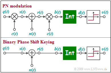
The graph above shows the equivalent circuit of "pseudo-noise" modulation ( ''Direct Sequence Spread Spectrum'', abbreviated '''DS-SS''') in the equivalent low-pass region. $n(t)$ denotes AWGN noise. | The graph above shows the equivalent circuit of "pseudo-noise" modulation ( ''Direct Sequence Spread Spectrum'', abbreviated '''DS-SS''') in the equivalent low-pass region. $n(t)$ denotes AWGN noise. | ||
| − | + | Below is sketched the low pass model of [[Modulation_Methods/Linear_Digital_Modulation#BPSK_.E2.80.93_Binary_Phase_Shift_Keying|"Binary Phase Shift Keying"]]. | |
| − | * | + | *The low-pass transmit signal $s(t)$ is set equal to the rectangular source signal $q(t) ∈ \{+1, -1\}$ with rectangular duration $T$ only for reasons of uniform representation. |
| − | * | + | *The integrator function can be written as follows: |
:$$d (\nu T) = \frac{1}{T} \cdot \hspace{0.03cm} \int_{(\nu -1 )T }^{\nu T} \hspace{-0.3cm} b (t )\hspace{0.1cm} {\rm d}t \hspace{0.05cm}.$$ | :$$d (\nu T) = \frac{1}{T} \cdot \hspace{0.03cm} \int_{(\nu -1 )T }^{\nu T} \hspace{-0.3cm} b (t )\hspace{0.1cm} {\rm d}t \hspace{0.05cm}.$$ | ||
| − | * | + | *The two models differ by multiplication by the $±1$-spread signal $c(t)$ at the transmitter and receiver, where only the degree of spread $J$ is known from $c(t)$ . |
| − | * | + | *For the solution of this exercise, the specification of the specific spreading sequence (M sequence or Walsh function) is not important. |
| − | + | What needs to be investigated is whether the lower BPSK model can also be applied in PN modulation and whether the BPSK error probability | |
| − | :$$p_{\rm B} = {\rm Q} \left( \hspace{-0.05cm} \sqrt { {2 \cdot E_{\rm B}}/{N_{\rm 0}} } \hspace{0.05cm} \right )$$ | + | :$$p_{\rm B} = {\rm Q} \left( \hspace{-0.05cm} \sqrt { {2 \cdot E_{\rm B}}/{N_{\rm 0}} } \hspace{-0.05cm} \right )$$ |
| − | + | is also valid for PN modulation, or how to modify the given equation. | |
| Line 27: | Line 27: | ||
| − | + | Hints: | |
| − | * | + | *This exercise belongs to the chapter [[Examples_of_Communication_Systems/Telecommunications_Aspects_of_UMTS|"Telecommunications Aspects of UMTS"]]. |
| − | * | + | *The CDMA method used in UMTS also goes by the name "PN modulation". |
| − | * | + | *The nomenclature used in this exercise is partly based on the chapter [[Modulation_Methods/Direct-Sequence_Spread_Spectrum_Modulation|"PN Modulation"]] in the book "Modulation Methods". |
Revision as of 22:53, 28 February 2023
The graph above shows the equivalent circuit of "pseudo-noise" modulation ( Direct Sequence Spread Spectrum, abbreviated DS-SS) in the equivalent low-pass region. $n(t)$ denotes AWGN noise.
Below is sketched the low pass model of "Binary Phase Shift Keying".
- The low-pass transmit signal $s(t)$ is set equal to the rectangular source signal $q(t) ∈ \{+1, -1\}$ with rectangular duration $T$ only for reasons of uniform representation.
- The integrator function can be written as follows:
- $$d (\nu T) = \frac{1}{T} \cdot \hspace{0.03cm} \int_{(\nu -1 )T }^{\nu T} \hspace{-0.3cm} b (t )\hspace{0.1cm} {\rm d}t \hspace{0.05cm}.$$
- The two models differ by multiplication by the $±1$-spread signal $c(t)$ at the transmitter and receiver, where only the degree of spread $J$ is known from $c(t)$ .
- For the solution of this exercise, the specification of the specific spreading sequence (M sequence or Walsh function) is not important.
What needs to be investigated is whether the lower BPSK model can also be applied in PN modulation and whether the BPSK error probability
- $$p_{\rm B} = {\rm Q} \left( \hspace{-0.05cm} \sqrt { {2 \cdot E_{\rm B}}/{N_{\rm 0}} } \hspace{-0.05cm} \right )$$
is also valid for PN modulation, or how to modify the given equation.
Hints:
- This exercise belongs to the chapter "Telecommunications Aspects of UMTS".
- The CDMA method used in UMTS also goes by the name "PN modulation".
- The nomenclature used in this exercise is partly based on the chapter "PN Modulation" in the book "Modulation Methods".
Fragebogen
Musterlösung
(1) Richtig ist der letzte Lösungsvorschlag:
- Es handelt sich hier um einen optimalen Empfänger.
- Ohne Rauschen ist Signal $b(t)$ innerhalb eines jeden Bits konstant gleich $+1$ oder $-1$.
- Aus der angegebenen Gleichung für den Integrator folgt, dass $d(\nu T)$ nur die Werte $±1$ annehmen kann:
- $$d (\nu T) = \frac{1}{T} \cdot \hspace{-0.1cm} \int_{(\nu -1 )T }^{\nu T} \hspace{-0.3cm} b (t )\hspace{0.1cm} {\rm d}t.$$
(2) Richtig ist wieder der letzte Lösungsvorschlag:
- Im rauschfreien Fall ⇒ $n(t) = 0$ kann auf die zweifache Multiplikation mit $c(t) ∈ \{+1, –1\} \ \Rightarrow \ c(t)^{2} = 1$ verzichtet werden,
- so dass das obere Modell mit dem unteren Modell identisch ist.
(3) Zutreffend ist nur der Lösungsvorschlag 1:
- Da beide Modelle im rauschfreien Fall identisch sind, muss nur das Rauschsignal angepasst werden: $n\hspace{0.05cm}'(t) = n(t) \cdot c(t)$.
- Die Vorschläge 2 und 3 sind dagegen nicht zutreffend: Die Integration muss weiterhin über $T = J \cdot T_{\rm c}$ erfolgen und die PN–Modulation verringert das AWGN–Rauschen nicht.
(4) Richtig ist der letzte Lösungsvorschlag.:
- Multipliziert man das AWGN–Rauschen mit dem hochfrequenten $±1$–Signal $c(t)$, so ist das Rauschen ebenfalls gaußförmig und weiß.
- Wegen $E[c^{2}(t)] = 1$ wird auch die Rauschvarianz nicht verändert. Die für BPSK gültige Gleichung
- $$p_{\rm B} = {\rm Q} \left( \hspace{-0.05cm} \sqrt { {2 \cdot E_{\rm B}}/{N_{\rm 0}} } \hspace{0.05cm} \right )$$
- ist somit auch bei der PN–Modulation anwendbar und zwar unabhängig vom Spreizfaktor $J$ und von der spezifischen Spreizfolge.
- ⇒ Bei AWGN–Rauschen wird also die Fehlerwahrscheinlichkeit durch Bandspreizung weder vergrößert noch verkleinert.
