Contents
Structure of the optimal Nyquist equalizer
In this section we assume the following block diagram of a binary system. In this regard, it should be noted:
- The Dirac source provides the message to be transmitted in binary bipolar form ⇒ amplitude coefficients $a_\nu \in \{ -1, \hspace{0.05cm}+1\}$. The source is assumed to be redundancy-free.
- The transmission pulse shape $g_s(t)$ is taken into account by the transmitter frequency response $H_{\rm S}(f)$. In all examples, $H_{\rm S}(f) = {\rm si}(\pi f T)$ is based ⇒ NRZ rectangular transmission pulses.
In some derivations, transmitter and channel are combined by the common frequency response $H_{\rm SK}(f) = H_{\rm S}(f) \cdot H_{\rm K}(f)$.
- The receiver filter $H_{\rm E}(f)$ is multiplicatively composed of the matched filter $H_{\rm MF}(f) = H_{\rm SK}^\star(f)$ and the transversal filter $H_{\rm TF}(f)$, at least it can be split up mentally in this way.
- The total frequency response between the Dirac source and the threshold decision should satisfy the first Nyquist condition. Thus, it must hold:
- $$H_{\rm S}(f) \cdot H_{\rm K}(f) \cdot H_{\rm MF}(f) \cdot H_{\rm TF}(f) = H_{\rm Nyq}(f) \hspace{0.05cm}.$$
- With this condition, there is no intersymbol interference and the maximum eye opening is obtained. Therefore, the detection SNR and system efficiency for binary signaling are:
- $$\rho_d = \frac{2 \cdot s_0^2 \cdot T}{\sigma_d^2} = \frac{2 \cdot s_0^2 \cdot T}{N_0}\cdot \frac{1}{\sigma_{d,\hspace{0.05cm} {\rm norm}}^2} \hspace{0.3cm}\Rightarrow \hspace{0.3cm} \eta = \frac{\rho_d }{\rho_{d,\hspace{0.05cm} {\rm max}}} = \frac{\rho_d }{2 \cdot s_0^2 \cdot T/N_0} = \frac{1}{\sigma_{d,\hspace{0.05cm} {\rm norm}}^2} \hspace{0.05cm}.$$
- The optimization task is therefore limited to determining the receiver filter $H_{\rm E}(f)$ such that the normalized noise power before the decision takes the smallest possible value:
- \[\sigma_{d,\hspace{0.05cm} {\rm norm}}^2 = \frac{\sigma_d^2}{N_0/ T} =T \cdot \int_{-\infty}^{+\infty} |H_{\rm E}(f)|^2 \,{\rm d} f \stackrel {!}{=} {\rm minimum}\hspace{0.05cm}.\]
$\text{Definition:}$ We refer to the configuration described here as Optimal Nyquist Equalization (ONE). Although this can also – and especially effectively – be applied to multi-level systems, we initially set $M = 2$.
Mode of action of the transversal filter
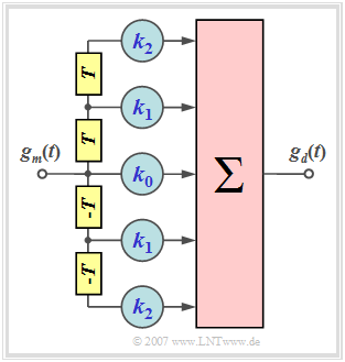
Let us first clarify the task of the symmetric transversal filter
- $$H_{\rm TF}(f) \hspace{0.4cm}\bullet\!\!-\!\!\!-\!\!\!-\!\!\circ \hspace{0.4cm} h_{\rm TF}(t) = \sum_{\lambda = -N}^{+N} k_\lambda \cdot \delta(t - \lambda \cdot T) $$
with the following properties:
- $N$ indicates the order of the filter ⇒ the graph shows a second order filter $(N=2)$.
- For the filter coefficients $k_{-\lambda} = k_{\lambda}$ ⇒ symmetric structure ⇒ $H_{\rm TF}(f)$ is real.
- $H_{\rm TF}(f)$ is thus completely determined by the coefficients $k_0$, ... , $k_N$ completely determined.
For the input pulse $g_m(t)$ we assume without restriction of generality that it is
- symmetric about $t=0$ (output of the matched filter),
- has the value $g_m(\nu)$ at times $\nu \cdot T$ and $-\nu \cdot T$, respectively.
Thus, the input pulse values are:
- $$\text{...}\hspace{0.2cm} , g_m(3),\hspace{0.15cm}g_m(2),\hspace{0.15cm}g_m(1),\hspace{0.15cm}\hspace {0.15cm}g_m(0),\hspace{0.15cm}g_m(1),\hspace{0.15cm}g_m(2),\hspace{0.15cm}g_m(3),\hspace{0.1cm} \text{...}\hspace{0.05cm}.$$
Consequently, for the basic transmitter pulse $g_d(t)$ at the filter output, the following values result at the time instants $\nu \cdot T$ with the abbreviations $g_0 =g_d(t= 0)$, $g_1 =g_d(t= \pm T)$, $g_2 =g_d(t= \pm 2T)$:
- $$ t = 0\hspace{-0.1cm}:\hspace{0.9cm}g_0 = k_0 \cdot g_m(0) + k_1 \cdot 2 \cdot g_m(1) \hspace{1.23cm}+k_2 \cdot 2 \cdot g_m(2),\hspace{0.05cm} $$
- $$ t = \pm T\hspace{-0.1cm}:\hspace{0.45cm}g_1 = k_0 \cdot g_m(1) + k_1 \cdot \big [g_m(0)+g_m(2)]+ k_2 \cdot [g_m(1)+g_m(3) \big ], $$
- $$ t = \pm 2T\hspace{-0.1cm}:\hspace{0.2cm}g_2 = k_0 \cdot g_m(2) + k_1 \cdot \big [g_m(1)+g_m(3)\big ]+ k_2 \cdot \big [g_m(2)+g_m(4)\big ] \hspace{0.05cm}. $$
From this system with three linearly independent equations, one can now determine the filter coefficients $k_0$, $k_1$ and $k_2$ in such a way that the basic transmitter pulse $g_d(t)$ has the following interpolation points:
- $$\text{...}\hspace{0.15cm} , g_3,\hspace{0.25cm}g_2 = 0 ,\hspace{0.15cm}g_1 = 0 ,\hspace{0.15cm}g_0 = 1,\hspace{0.15cm}g_1 = 0 ,\hspace{0.15cm}g_2 = 0 ,\hspace{0.25cm}g_3 ,\hspace{0.15cm} \text{...}$$
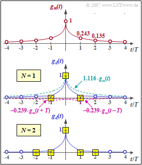
$\text{Example 1:}$ We assume the symmetrical input signal according to the upper diagram in the graph. With the abbreviation $g_m(\nu)= g_m(\pm \nu \cdot T)$ there are the following samples at the distance of the symbol duration $T$:
- $$g_m(t) = {\rm e}^{ - \sqrt{2 \hspace{0.05cm} \cdot \hspace{0.05cm}\vert\hspace{0.05cm} t \hspace{0.05cm} \vert /T} }\hspace{0.3cm} \Rightarrow \hspace{0.3cm} g_m(0) = 1 ,\hspace{0.35cm}g_m(1)= 0.243,\hspace{0.35cm}g_m(2)= 0.135,\hspace{0.35cm}g_m(3)= 0.086, \hspace{0.35cm}g_m(4)= 0.059 \hspace{0.05cm}.$$
For the output pulse $g_d(t =0) = 1$ and $g_d(t =\pm T) = 0$ should be valid. For this purpose, a first-order delay filter with coefficients $k_0$ and $k_1$ is suitable, which must satisfy the following conditions:
- $$t = \pm T\hspace{-0.1cm} : \hspace{0.2cm}g_1 = k_0 \cdot 0.243 + k_1 \cdot \big [1.000 +0.135 \big ] = 0\hspace{0.3cm}\Rightarrow \hspace{0.3cm}{k_1} = -0.214 \cdot {k_0}\hspace{0.05cm},$$
- $$ t = 0 \hspace{-0.1cm} : \hspace{0.6cm}g_0 = k_0 \cdot 1.000 + k_1 \cdot 2 \cdot 0.243= 1\hspace{0.3cm}\Rightarrow \hspace{0.3cm}0.896 \cdot {k_0} = 1 \hspace{0.05cm}.$$
From this, the optimal filter coefficients $k_0 = 1.116$ and $k_1 = 0.239$ are obtained.
- The middle diagram shows that thus the first precursor and the first trailer can be compensated and at the same time $g_d(0) =1$ is valid (yellow background).
- However, the further basic transmitter pulse values (blue circles) are different from zero and cause intersymbol interference.
The lower diagram shows that with a second order filter $(N = 2)$ zero crossings are forced at $\pm T$ and at $\pm 2T$ if the coefficients $k_0 = 1.127$, $k_1 = 0.219$ and $k_2 = 0.075$ are suitably chosen. The system of equations for determining the optimal coefficients is thereby:
- $$t = 0\hspace{-0.1cm}:\hspace{0.85cm}g_0 = k_0 \cdot 1.000 + k_1 \cdot 2 \cdot 0.243 + k_2 \cdot 2 \cdot 0.135 = 1\hspace{0.05cm},$$
- $$t= \pm T\hspace{-0.1cm}:\hspace{0.45cm}g_1 = k_0 \cdot 0.243 + k_1 \cdot \big [1.000+0.135 \big ]+ k_2 \cdot \big [0.243+0.086 \big ] = 0\hspace{0.05cm},$$
- $$t = \pm 2 T\hspace{-0.1cm}:\hspace{0.2cm}g_2 = k_0 \cdot 0.135 + k_1 \cdot \big [0.243+0.086\big ]+ k_2 \cdot \big [1.000 + 0.059 \big ]= 0 \hspace{0.05cm}.$$
$\text{Conclusion:}$ The results can be generalized as follows:
- With an $N$–th order delay filter, the main value $g_d(0)$ can be made one (normalized), and the first $N$ trailers $g_{\nu}$ and the first $N$ precursors $g_{-\nu}$ can be made zero.
- Further precursors and trailers $(\nu \gt N)$ cannot be compensated in this way. It is even possible that the precursors and trailers outside the compensation range are enlarged or even new ones are created.
- In the limit $N \to \infty$ (in practice this means: a filter with very many coefficients) a complete Nyquist equalization and thus an intersymbol interference free transmission is possible.
Description in the frequency domain
The fact that the optimal Nyquist equalizer is multiplicatively derived from
- the matched filter $H_{\rm MF}(f) = H_{\rm S}^\star (f)\cdot H_{\rm K}^\star(f)$ – i.e. matched to the basic receiver pulse $g_r(t)$ – and
- a transversal filter $H_{\rm MF}(f)$ with infinitely many filter coefficients
follows from the first Nyquist criterion. By applying the "calculus of variations", the frequency response of the transversal filter is obtained – see [TS87][1]:
- $$H_{\rm TF}(f) = \frac{1}{\sum\limits_{\kappa = -\infty}^{+\infty} |H_{\rm SK}(f - \frac{\kappa}{T}) |^2} \hspace{0.3cm}{\rm{mit}}\hspace{0.3cm}H_{\rm SK}(f) = H_{\rm S}(f)\cdot H_{\rm K}(f) \hspace{0.05cm}.$$
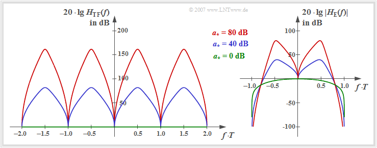
The left graph shows the function $20 \cdot \lg \ H_{\rm TF}(f)$ in the range $| f | \le 1/T$. This assumes rectangular NRZ transmission pulses and a coaxial cable with the characteristic cable attenuation $a_\star$.
One can see from the above equation and the left graph:
- $H_{\rm TF}(f)$ is real, which results in the symmetrical structure of the transversal filter: $k_{-\lambda} =k_{+\lambda} $.
- $H_{\rm TF}(f)$ is at the same time a function periodic with frequency $1/T$.
- The coefficients are thus obtained from the Fourier series (applied to the spectral function):
- $$k_\lambda =T \cdot \int_{-1/(2T)}^{+1/(2T)}\frac{\cos(2 \pi f \lambda T)} {\sum\limits_{\kappa = -\infty}^{+\infty} |H_{\rm SK}(f - {\kappa}/{T}) |^2} \hspace{0.2cm} {\rm d} f \hspace{0.25cm}\Rightarrow \hspace{0.25cm}H_{\rm TF}(f) = \sum\limits_{\lambda = -\infty}^{+\infty} k_\lambda \cdot {\rm e}^{-{\rm j}2 \pi f \lambda T}\hspace{0.05cm}.$$
The right graph shows the frequency response $20 \cdot \lg \ |H_{\rm E}(f)|$ of the entire receiver filter including the matched filter. It holds:
- $$H_{\rm E}(f) = H_{\rm MF}(f) \cdot H_{\rm TF}(f) = \frac{H_{\rm SK}^{\star}(f)}{\sum\limits_{\kappa = -\infty}^{+\infty} |H_{\rm SK}(f - {\kappa}/{T}) |^2}.$$
To these representations it is to be noted:
- For $a_\star = 0 \ \rm dB$ (ideal channel, green zero line) the transversal filter $H_{\rm TF}(f)$ can be omitted and it is valid for NRZ rectangular pulses as already derived in the section "Optimal binary receiver – "Matched Filter" realization":
- $$H_{\rm E}(f) =H_{\rm S}(f) = {\rm si} (\pi f T).$$
- While the transversal filter frequency response $H_{\rm TF}(f)$ is symmetrical to the Nyquist frequency $f_{\rm Nyq} = 1/(2T)$ at $a_\star \ne 0 \ \rm dB$, this symmetry is no longer given for the receiver filter overall frequency response $H_{\rm E}(f)$.
- The maxima of the frequency responses $H_{\rm TF}(f)$ and $|H_{\rm E}(f)|$ depend significantly on the characteristic cable attenuation $a_\star$. From the blue and red function curves, respectively, can be read:
- $$a_{\star} = 40\,{\rm dB}\hspace{-0.1cm}:\hspace{0.2cm}{\rm Max}\big[H_{\rm TF}(f)\big]\hspace{0.1cm} \approx 80\,{\rm dB}, \hspace{0.2cm}{\rm Max}\big[\ |H_{\rm E}(f)| \ \big] \approx 40\,{\rm dB}\hspace{0.05cm},$$
- $$a_{\star} = 80\,{\rm dB}\hspace{-0.1cm}:\hspace{0.2cm}{\rm Max}\big[H_{\rm TF}(f)\big] \approx 160\,{\rm dB}, \hspace{0.2cm}{\rm Max}\big[\ |H_{\rm E}(f)|\ \big] \approx 80\,{\rm dB}\hspace{0.05cm}.$$
Approximation of the optimal Nyquist equalizer
We now consider the overall frequency response between the Dirac source and the decision.
- This is made up multiplicatively of the frequency responses of the transmitter, channel and receiver.
- According to the derivation, the total frequency response must satisfy the Nyquist condition:
- $$H_{\rm Nyq}(f) = H_{\rm S}(f) \cdot H_{\rm K}(f) \cdot H_{\rm E}(f) = \frac{|H_{\rm SK}(f)|^2}{\sum\limits_{\kappa = -\infty}^{+\infty} |H_{\rm SK}(f - {\kappa}/{T}) |^2}\hspace{0.05cm}.$$
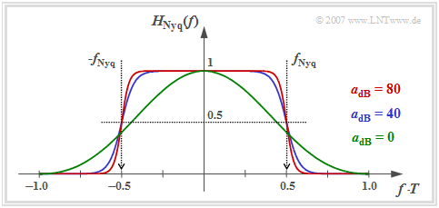
The graph shows the following properties of the optimal Nyquist equalizer (ONE):
- If the cable attenuation is sufficiently large $(a_\star \ge 10 \ \rm dB)$, the overall frequency response can be described with good approximation by the cosine rolloff low-pass filter.
- Je größer $a_\star$ ist, desto kleiner ist der Rolloff–Faktor $r$ und um so steiler verläuft der Flankenabfall. Für die charakteristische Kabeldämpfung $a_\star = 40 \ \rm dB$ (blaue Kurve) ergibt sich $r \approx 0.4$, für $a_\star = 80 \ \rm dB$ (rote Kurve) $r \approx 0.18$.
- Oberhalb der Frequenz $f_{\rm Nyq} \cdot (1 + r)$ besitzt $H_{\rm Nyq}(f)$ keine Anteile. Bei idealem Kanal ⇒ $a_\star = 0 \ \rm dB$ (grüne Kurve) reicht $H_{\rm Nyq}(f)= {\rm si}^2(\pi f T)$ allerdings theoretisch bis ins Unendliche.
Das interaktive Applet Frequenzgang und Impulsantwort verdeutlicht unter anderem die Eigenschaften des Cosinus–Rolloff–Tiefpasses.
Berechnung der normierten Störleistung
Wir betrachten nun noch die (normierte) Störleistung am Entscheider. Für diese gilt:
- $$\sigma_{d,\hspace{0.05cm} {\rm norm}}^2 = \frac{\sigma_d^2}{N_0/ (2T)} =T \cdot \int_{-1/(2T)}^{+1/(2T)} |H_{\rm E}(f)|^2 \,{\rm d} f .$$
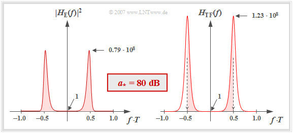
- Das linke Diagramm der Grafik zeigt $|H_{\rm E}(f)|^2$ im linearen Maßstab für die charakteristische Kabeldämpfung $a_\star = 80 \ \rm dB$. Beachten Sie, dass $|H_{\rm E}(f = 0)|^2 = 1$ ist.
- Da die Frequenz in dieser Darstellung auf $1/T$ normiert wurde, entspricht die normierte Störleistung genau der (rot hinterlegten) Fläche unter dieser Kurve. Die numerische Auswertung ergibt:
- $$\sigma_{d,\hspace{0.05cm} {\rm norm}}^2 = 1.68 \cdot 10^7\hspace{0.3cm}\Rightarrow \hspace{0.3cm} 10 \cdot {\rm lg}\hspace{0.1cm}\sigma_{d,\hspace{0.05cm} {\rm norm}}^2 \approx 72.25\,{\rm dB} \hspace{0.05cm}.$$
- Es kann gezeigt werden, dass die normierte Störleistung allein mit dem Transversalfilter–Frequenzgang $H_{\rm TF}(f)$ berechnet werden kann, wie in der rechten Grafik dargestellt:
- $$\sigma_{d,\hspace{0.05cm} {\rm norm}}^2 = T \cdot \int_{-1/(2T)}^{+1/(2T)} H_{\rm TF}(f) \,{\rm d} f \hspace{0.3cm}(= k_0)\hspace{0.05cm}.$$
- Die roten Flächen sind in beiden Bildern exakt gleich.
$\text{Fazit:}$ Die normierten Störleistung des optimalen Nyquistentzerrers ist gleich dem Fourierkoeffizienten $k_0$, wenn man den reellen, symmetrischen und periodischen Transversalfilter–Frequenzgang $H_{\rm TF}(f)$ als Fourierreihe darstellt.
- In der zweiten Spalte der Tabelle ist $10 \cdot \lg \ (k_0)$ abhängig von der charakteristischen Kabeldämpfung $a_\star$ eines Koaxialkabels angegeben.
- Aufgrund der gewählten Normierung gilt die Tabelle auch für redundanzfreie Mehrstufensysteme; hierbei bezeichnet $M$ die Stufenzahl.
- Die Koeffizienten $k_1$, $k_2$, $k_3$, ... des Transversalfilters weisen für $a_\star \ne 0 \ \rm dB$ alternierende Vorzeichen auf.
- Für $a_\star = 40 \ \rm dB$ sind vier Koeffizienten betragsmäßig größer als $k_0/10$, für $a_\star = 80 \ \rm dB$ sogar sieben.
Vergleich anhand des Systemwirkungsgrades
Für einen Systemvergleich eignet sich der Systemwirkungsgrad, der das erreichbare Detektions–SNR $\rho_d$ in Bezug zum maximalen SNR $\rho_{d, \ {\rm max}}$ setzt, das allerdings nur bei idealem Kanal $H_{\rm K}(f) \equiv 1$ erreichbar ist. Für den Systemwirkungsgrad gilt bei $M$–stufiger Übertragung und optimaler Nyquistentzerrung:
- $$\eta = \frac{\rho_d}{s_0^2 \cdot T / N_0}=\frac{{\rm log_2}\hspace{0.1cm}M}{(M-1)^2 \cdot k_0}.$$
Die (normierte) Störleistung $k_0$ kann aus der Tabelle auf der letzten Seite abgelesen werden. Beachten Sie die Normierung der charakteristischen Kabeldämpfung $a_\star$ in der ersten Spalte. Die folgende Tabelle aus [TS87][1] ermöglicht einen Systemvergleich für die charakteristische Kabeldämpfung $a_\star = 80 \ \rm dB$.
Verglichen werden:
- der gaußförmige Gesamtfrequenzgang $\text{(GTP)}$, der auch bei Optimierung zu einem impulsinterferenzbehafteten System führt,
- der optimale Nyquistentzerrer $\text{(ONE)}$, mit dem Impulsinterferenzen per se ausgeschlossen werden.
$\text{Fazit:}$ Die Ergebnisse dieses Systemvergleichs können wie folgt zusammengefasst werden:
- Im binären Fall $(M = 2)$ ist das impulsinterferenzfreie System $\text{(ONE)}$ um etwa $6 \ \rm dB$ besser als das impulsinterferenzbehaftete System $\text{(GTP)}$.
- Wendet man die optimale Nyquistentzerrung bei Mehrstufensystemen an, so ist gegenüber $\text{GTP}$ ein weiterer, deutlicher Störabstandsgewinn möglich. Für $M =4$ beträgt dieser Gewinn etwa $18.2 \ \rm dB$.
- Das schmalbandige $\text{GTP}$–System kann allerdings deutlich verbessert werden, wenn man einen Empfänger mit Entscheidungsrückkopplung verwendet. Dieser wird im nächsten Kapitel behandelt.
Wir verweisen an dieser Stelle auf das interaktive Applet Lineare Nyquistentzerrung.
Aufgaben zum Kapitel
Exercise 3.6: Transversal Filter of the Optimal Nyquist Equalizer
Exercise 3.6Z:Optimum Nyquist Equalizer for Exponential Pulse
Exercise 3.7: Optimal Nyquist Equalization once again
Exercise 3.7Z: Regenerator Field Length
References

