Contents
- 1 # OVERVIEW OF THE FOURTH MAIN CHAPTER #
- 2 Requirements for third-generation mobile communications systems
- 3 The IMT 2000 standard
- 4 Historical development of UMTS
- 5 Frequency allocation for UMTS
- 6 Full duplex
- 7 Properties of the UMTS radio channel
- 8 Frequency– and time–selective fading
- 9 UMTS–Dienste
- 10 Security aspects
- 11 Aufgaben zum Kapitel
# OVERVIEW OF THE FOURTH MAIN CHAPTER #
$\rm U$niversal $\rm M$obile $\rm T$elecommunications $\rm S$ystem $\rm (UMTS)$ is a third-generation mobile communications system, which, when it was introduced, was intended to be a forward-looking alternative to the mobile communications systems used until then. Compared with GSM, it not only offers higher-quality speech, but also a variety of enhanced services and functionalities thanks to its faster and packet-switched transmission.
UMTS was standardized in the late 1990s as part of a collaboration between the "International Telecommunication Union" $\rm (ITU)$ and the 3GPP Forum $($"3rd Generation Partnership Project"$)$ and has been commercially available in Europe since 2004.
⇒ In 2011 $($when this chapter was conceived$)$ about 200 million subscribers worldwide were using UMTS or similar third-generation mobile communications systems.
⇒ In 2022 $($when this chapter was revised again as part of the English translation$)$ a global report by the network equipment industry has identified more than a hundred operators that have either completed 3G switch-off alongside 2G switch-off, are planning to do so or are in the process of doing so, in order to use the spectrum this frees up for "$\rm LTE$", $\rm 5G$ or technology-neutral.
- 28 operators in 17 countries and territories have now completed 3G switch-off.
- Six operators in six countries and territories currently have 3G switch-off underway.
- Another 46 operators in 31 countries have 3G shutdowns planned for the very near future.
- It is also interesting to note from this report that in some countries the UMTS switch-off is being pushed even harder than that of the 2G standard, which is about ten years older "$\rm GSM$".
⇒ We have chosen to keep this chapter in our $\rm LNTwww$ despite this negative forecast, since understanding the underlying CDMA technology also facilitates students' understanding of other communications engineering problems. Korrektur: Hier muss ich noch mit Kollegen reden.
This chapter includes in detail:
- UMTS as a third generation mobile communications system,
- the services and security aspects in UMTS,
- the UMTS network architecture,
- the physical, logical and transport channels and their interactions,
- the cellular architecture in UMTS and its mechanisms,
- the speech and channel coding used in UMTS,
- the band spreading and CDMA as the basis of UMTS,
- the radio resource management and power control in UMTS networks,
- the further developments of UMTS such as HSDPA and HSUPA,
- an outlook on Long Term Evolution (LTE), the buzzword of the fourth generation.
Requirements for third-generation mobile communications systems
The main motivation for the development of third-generation mobile communications systems was the realization that second-generation systems could not satisfy the bandwidth requirements for the use of multimedia services.
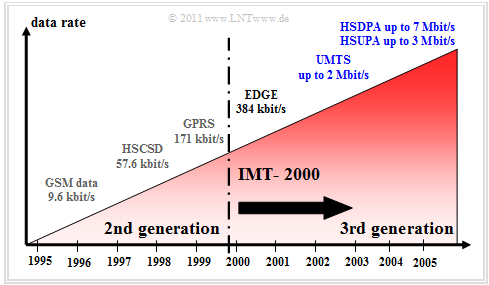
The graph shows the development of mobile radio systems since 1995 in terms of performance or data transmission rate as seen in 2007:
- The specified data rates for HSUPA $($uplink, up to $\text{3 Mbit/s)}$ and HSDPA $($downlink, up to $\text{7 Mbit/s)}$ were realistic for 2006/2007.
- In contrast, the specifications stated maximum values for the uplink $\text{5.8 Mbit/s}$ and for the downlink $\text{14.4 Mbit/s}$ (i.e., significantly higher maximum values), but these will probably not be achievable in practice.
The third-generation mobile communications systems were to have greater bandwidth than the "GSM" already established at that time and sufficient reserve capacity to ensure high quality of service even in the face of constantly growing demands.
In the development of the third generation systems, the International Telecommunication Union (ITU) has played an important role. Among other things, it created a catalog of requirements that defined their characteristics. This catalog of requirements includes the following general conditions:
- High data rates from $\text{144 kbit/s}$ (standard) to $\text{2 Mbit/s}$ (in-door),
- symmetric and asymmetric data transmission (IP services),
- circuit-switched and packet-switched transmission,
- high speech quality and high spectral efficiency,
- seamless transition to and from second-generation systems,
- global reachability and distribution,
- applications independent of the network used (virtual home environment).
The IMT 2000 standard
In 1992, the International Telecommuncation Union (ITU) launched the $\rm IMT\hspace{-0.1cm}-\hspace{-0.1cm}2000$ $($International Mobile Telecommunications at 2000 MHz$)$ standard to enable the above requirements. This comprises a number of different third-generation mobile communications systems that have been converged during the standardization process to enable the development of common terminals for all these standards.
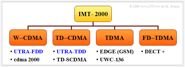
In order to take into account nationally different preliminary work and to allow network operators to continue using existing network architectures to some extent, IMT-2000 includes several individual standards. These can be roughly divided into four categories:
- $\rm W-CDMA$: This includes the FDD component of the European UMTS standard as well as the American cdma2000 system.
- $\rm TD-CDMA$: This group includes the TDD component of UMTS as well as the Chinese TD-SCDMA, which is now integrated into the UMTS TDD standard.
- $\rm TDMA$: A further development of the GSM offshoot EDGE and its American counterpart UWC-136, also known as DS-AMPS.
- $\rm FD-TDMA$: The further development of the European cordless telephony standard DECT (Digital Enhanced Cordless Telecommunication).
In the following, we focus on the European-developed system $\rm UMTS$ (Universal Mobile Telecommunications System), which supports the first two standards as well as $\rm TD-CDMA$ of the IMT-2000 system family.
Historical development of UMTS
The following is some data on the historical development of UMTS and the techniques used. More information can be found, for example, at this "internet link".
- 1940-1950 First military applications of signal spreading techniques.
- 1949 First outlines of the CDMA process by C. E. Shannon and J. R. Pierce.
- 1970 Various CDMA developments for military systems, e.g. GPS.
- 1989-1992 Basic research on the characteristics of future mobile radio systems within the EU program RACE-1.
(Research, Analysis, Communication, Evaluation). - 1992 First consideration of the IMT-2000 standard by the ITU.
- 1992-1995 EU program RACE-2 focusing on "development of system concepts" - based on the results of RACE-1.
- 1996 Foundation of the UMTS Forum in Zurich - renaming of the planned European standard "W-CDMA" to "UMTS".
- 1998 Adoption of the two modes W-CDMA and TD-CDMA into the UMTS standard at the ETSI-SMG meeting in Paris.
- 1998 Establishment of the 3gpp forum (3rd Generation Partnership Project) by the ETSI-SMG, T1P1, ARIB TTC and TTA committees.
- 1999 Adoption of the UMTS-R99 standard (Release 1999) by ETSI. This is considered the basis for the first available UMTS terminals.
- 2001 Adoption of Release 4 as a further development of UMTS-R99: Quality of Service (QoS) is now supported at the radio interface and in the fixed network.
- 2001 First commercial UMTS network of the Norwegian company TELENOR.
- 2002 Adoption of UMTS Release 5: Architecture based on the GSM fixed network is replaced by a fully IP-based fixed network.
- 2002 First UMTS voice and data link from Nortel Networks and Qualcomm. These companies are considered pioneers in the implementation of UMTS technology.
- 2004 Adoption of UMTS Release 6, a standard that provides improved QoS for the user and more effective resource management for the provider.
$\text{Summary of the historical development of UMTS}$
With UMTS, too, more than a decade has passed between the first conceptual considerations and the final introduction.
This was similar to the introduction of other communications systems, such as
- "ISDN" (Integrated Services Digital Network),
- "DSL" (Digital Subscriber Line),
- "GSM" (Global System for Mobile Communications).
Frequency allocation for UMTS
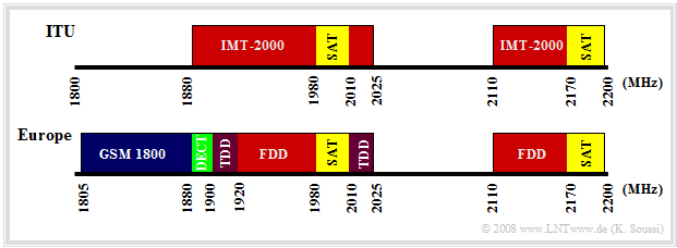
The International Telecommunication Union (ITU) is responsible for allocating bandwidths and frequency bands for communications systems. In the case of UMTS in particular, however, there are discrepancies between the European and ITU frequency allocations, as some frequency bands were already occupied by other mobile communications systems in some countries. The graphic shows the European (bottom) and the ITU frequency assignments (top).
Here, this means:
- $\rm GSM \ 1800$ - frequency band for the downlink of GSM 1800,
- $\rm SAT$ – satellite-based systems
(each $\text{30 MHz}$ for uplink and downlink), - $\rm DECT$ – Digital Enhanced Cordless Telecommunications
, - $\rm UTRA–FDD$ – UMTS Terrestrial Radio Access–Frequency Division Duplex,
- $\rm UTRA–TDD$ – UMTS Terrestrial Radio Access–Time Division Duplex.
$\rm UTRA-FDD$ – or $\rm FDD$ – for short, consists of twelve paired uplink and downlink frequency bands of $\text{5 MHz}$ bandwidth each. The frequency bands are located in Europe
- between $\text{1920 MHz}$ and $\text{1980 MHz}$ in the uplink, as well as.
- between $\text{2110 MHz}$ and $\text{2170 MHz}$ in the downlink.
In contrast, $\rm UTRA-TDD$ – or $\rm TDD$ – for short, consists of five frequency bands of $\text{5 MHz}$ bandwidth each, in which both uplink and downlink data are to be transmitted using time division multiplexing.
- The frequencies between $\text{1900 MHz}$ and $\text{1920 MHz}$ (four channels) and between $\text{2020 MHz}$ and $\text{2025 MHz}$ (one channel) are reserved for TDD.
- The band between $\text{2010 MHz}$ and $\text{2020 MHz}$ has not been licensed yet and is therefore not used in Germany either.
Full duplex
In order to separate the two transmission directions uplink and downlink, two different operating modes are supported in UMTS. A distinction is made between:
- UMTS Terrestrial Radio Access Frequency Division Duplex (UTRA-FDD),
- UMTS Terrestrial Radio Access Time Division Duplex (UTRA-TDD).
The main difference between these two modes can be seen in the physical layer of the protocol stack. The two methods differ in both their duplex and multiple access methods.
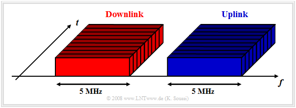
In $\rm UTRA-FDD$ mode - as shown in the above graphic - the uplink and downlink data are transmitted simultaneously on different but corresponding paired frequency blocks at $\text{5 MHz}$ each. It should be noted that:
- Data from different subscribers is transmitted and received on the same frequency band.
- The use of different CDMA spreading codes enables the separation of the respective subscriber data.
- The TDMA method is also used to realize periodic functions such as power control.
- The FDMA method can be used in addition to CDMA and TDMA if the network operator has more than one frequency channel.
FDD mode is used only in Europe and mostly only for symmetrical services whose bandwidth requirements in the uplink and downlink are approximately the same. This is the case for voice communications or video telephony, for example.
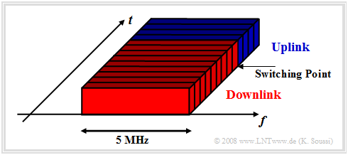
In $TRA-TDD$ mode, uplink and downlink data are transmitted in the same frequency band. In this case, uplink and downlink are separated in time, as shown in the following diagram. Furthermore:
- The switching point (Switching Point) can be flexibly selected depending on the data volume ratio between uplink and downlink.
- In TDD mode, the subscribers are identified both by the spreading code (as in FDD) and by the time slot.
- If the network operator has several frequency channels, FDMA can be used in addition to CDMA and TDMA, as with FDD.
TDD mode is not currently used in Europe and, once introduced, will mainly be used for asymmetric services (for example: downloads or surfing the Internet) where the data volumes of downlink and uplink differ significantly.
Properties of the UMTS radio channel
In the UMTS radio channel, in addition to interference from other subscribers and noise, a number of unpredictable, interfering and distorting effects occur, which also change over time.
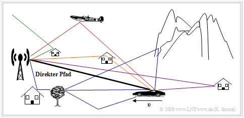
Due to reflections as well as scattering and diffraction from objects, the transmitted signal experiences multipath scattering.
- The signal reaches the receiver not only via the direct path, but via several paths with different propagation times and different attenuation.
- The multipath scattering is influenced by the environment, but additionally also by a possible movement of the subscriber, as indicated in the graph by the movement speed $v$ .
The path loss goes back to propagation properties of electromagnetic waves - see page "Common Path Loss Model" in the book "Mobile Communication". For the study of this attenuation phenomenon, we assume a simplified path loss model. This states:
- The received power of a radio signal decreases with distance $d$ by $d^{-γ}$, where $γ$ is a medium-dependent constant of the radio propagation wave.
- Accounting for constructive or destructive ground reflections, the constant $γ$ below the "break point" $d_0$ takes values between $2$ and $3$ .
- Above this characteristic point, the reflection effects increase and the propagation constant $γ$ grows to values between $3.5$ and $4$ .
$\text{Example 1:}$ Shown on the right is the path loss (in dB) as a function of distance $d$. In this example, the constant $α_0 = 10^{-5}$ $($also $50 \ \rm dB)$ is set and the break point is at $d_0 = \ \rm 100 \ m$.
- In the left-hand range $(d \ll d_0)$ $γ \approx 2$ holds.
- For $d \gg d_0$ on the other hand $γ \approx 4$.
- In the region around $d = d_0$ the propagation constant increases continuously from $γ = 2$ to $γ = 4$ .
Frequency– and time–selective fading
An essential property of the mobile radio channel is the so-called fading . This is caused by time-varying shadowing and by possible movements of the mobile subscriber.
In the book "Mobile Communications" this type of signal degradation is discussed in detail.
Here follows only a brief summary. One distinguishes on the one hand:
- Fast fading or short term fading with short term drops in received power in the microsecond range,
- Long term fading - i.e. only slow changes (mostly) in the seconds range.
Fast fading mainly affects systems with large symbol durations, i.e. small bandwidths. However, since the bandwidth of UMTS is much larger than that of GSM, this system is less susceptible to fast fading.
Furthermore, fading can also be classified as follows:
- Frequency selective fading is caused by multipath scattering over paths with different delay times. As a result of this fading, different frequency components are attenuated differently by the power transfer function $|H_{\rm K}(f)|^2$ of the channel.
- Time selective fading occurs due to a relative motion between transmitter and receiver. This causes frequency shifts depending on the direction of movement (towards or away from the transmitter) which are physically described by the Doppler effect .
The fading characteristics "frequency selective" and "time selective" shall now be explained in more detail, in particular it will be explained under which conditions which of these fading types are to be expected. At this point we also refer to the two interactive applets
$\text{Kennzeichen von frequenzselektivem Fading:}$
- Durch den Empfang verschiedener Streukomponenten mit unterschiedlichen Verzögerungszeiten entsteht eine Mehrwegeverbreiterung (englisch: Delay Spread ) $T_{\rm V}$, definiert als Differenz zwischen maximaler und minimaler Verzögerungszeit. Der Kehrwert hiervon ergibt näherungsweise die Kohärenzbandbreite $B_{\rm K}$.
- Man spricht dann von frequenzselektivem Fading, wenn die Kohärenzbandbreite $B_{\rm K}$ sehr viel kleiner ist als die Signalbandbreite $B_{\rm S}$. Als Folge werden verschiedene Frequenzanteile durch den Kanal unterschiedlich gedämpft, woraus lineare Verzerrungen resultieren.
$\text{Kennzeichen von zeitselektivem Fading:}$
- Beim zeitselektiven Fading entsteht eine so genannte Dopplerverbreiterung (englisch: Doppler Spread ) $B_{\rm D}$, die als Differenz zwischen der maximal und der minimal auftretenden Dopplerfrequenz definiert ist.
- Deren Kehrwert bezeichnet man als die Korrelationsdauer $T_{\rm D} = {1}/{B_{\rm D} }$. In manchen Literaturstellen wird diese Größe auch als Kohärenzzeit bezeichnet. Bei UMTS tritt immer dann zeitselektives Fading auf, wenn die Korrelationsdauer $T_{\rm D}$ sehr viel kleiner ist als die Chipdauer $T_{\rm C}$.
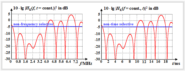
$\text{Beispiel 2:}$ Die linke Grafik verdeutlicht den Unterschied zwischen frequenzselektivem und nicht frequenzselektivem Fading:
- Dargestellt ist die Leistungsübertragungsfunktion $\vert H_{\rm K}(f, t)\vert ^2$ des Kanals zu einer festen Zeit $t$.
- Während blau nichtfrequenzselektives Fading mit $-5 \ \rm dB$ eingezeichnet ist, zeigt die rote Kurve in der linken Grafik ein Beispiel von frequenzselektivem Fading.
- Unterschiedliche Frequenzanteile werden dabei unterschiedlich gedämpft.
Die rechte Grafik zeigt schematisch zeitselektives Fading:
- Aufgetragen ist hier die Leistungsübertragungsfunktion $\vert H_{\rm K}(f, t) \vert ^2$ des Kanals für eine feste Frequenz $f$.
- Die blaue Kurve gilt für nicht zeitselektives Fading: Zu jeder Zeit wird das Signal um $5 \ \rm dB$ gedämpft.
UMTS–Dienste
Die Einführung von UMTS hat sich unter anderem die Erweiterung und Diversifikation der angebotenen Mobilfunkdienste zum Ziel gesetzt. Ein UMTS–fähiges Endgerät muss zusätzlich zu den klassischen Diensten (Sprachübertragung, Messaging, usw.) eine Reihe komplexerer multimedialer Anwendungen und Funktionen unterstützen.
Man kann diese Dienste – je nach Anwendung – in sechs Hauptkategorien unterteilen:
- Information : Internet–Surfen (Info–on–demand), Online–Printmedien,
- Kommunikation : Video– und Audiokonferenz, Fax, ISDN, Messaging,
- Unterhaltung : Mobile TV, Mobile Radio, Video–on–Demand, Online–Gaming,
- Geschäftlicher Bereich : Interaktives Einkaufen, E–Commerce,
- Technischer Bereich : Online–Betreuung, Distributionsservice (Sprache und Daten),
- Medizinischer Bereich : Telemedizin.
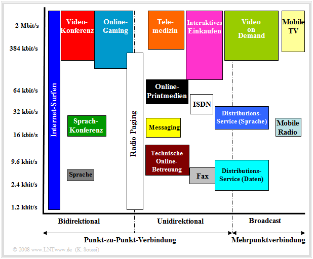
$\text{Beispiel 3:}$ In der Abbildung sind die UMTS–Dienste nach verschiedenen Merkmalen klassifiziert:
- nach Datenrate in vertikaler Richtung,
- nach Art der Verbindung (bidirektional, unidirektional, Broadcast) in horizontaler Richtung.
Graphik weg!!!
Anmerkungen:
- Die Höhe eines Kästchens gibt (in etwa) den Bereich für die erforderliche Datenrate an.
- Die Breite deutet näherungsweise auf den Datenumfang hin.
Security aspects
Die Sicherheitsmerkmale in UMTS–Netzen basieren auf den gleichen Prinzipien wie bei GSM. Allerdings wurden einige GSM–Sicherheitsfunktionen entfernt, ersetzt oder ausgebaut. Dadurch wurden
- die Verschlüsselungsalgorithmen robuster,
- die Authentifizierungsalgorithmen strenger und
- die Kriterien zur Vertraulichkeit eines Teilnehmers enger.
Die wesentlichen von GSM übernommenen Sicherheitsstandards bei UMTS sind:
- Authentifizierung des Teilnehmers,
- Vertraulichkeit der Teilnehmeridentität,
- Verschlüsselung der Funkschnittstelle.
Zusätzlich zu diesen wurden bei UMTS noch weitere Sicherheitsmaßnahmen beachtet:
- Gegenseitige Authentifizierung, um die Nutzung falscher Basisstationen zu vermeiden,
- Verschlüsselung der Verbindung zwischen Basisstation und zugehörigem Kontrollknoten,
- Verschlüsselung und Authentifizierung der Sicherheitsdaten bei der Übertragung,
- Mechanismen zur Aktualisierung der Sicherheitsmerkmale.
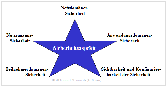
Man kann die oben aufgeführten Sicherheitsmaßnahmen entsprechend der Grafik klassifizieren.
Man unterscheidet Sicherheitskonzepte für
- den sicheren Netzzugang (Network Access Security) für jeden Teilnehmer,
- die Netzdomäne (Network Domain Security) – ein sicherer Austausch von Kontrolldaten zwischen den Knoten innerhalb der Netzdomäne wird sichergestellt,
- die Teilnehmerdomäne (User Domain Security) – der Zugang zu den Endgeräten wird sichergestellt,
- die Anwendungsdomäne (Application Domain Security) – der sichere Austausch zwischen Anwendungen der Teilnehmerendgeräte und der Netzanbieter wird garantiert.
Der UMTS–Teilnehmer kann jederzeit erkennen, welche dieser Sicherheitsmaßnahmen in Betrieb sind und welche davon für bestimmte Dienste benötigt werden. Man spricht in diesem Zusammenhang von Sichtbarkeit und Konfigurierbarkeit der Sicherheit.
Aufgaben zum Kapitel
Aufgabe 4.1: Verschiedene Duplexverfahren bei UMTS
Aufgabe 4.2: Grundlegendes zum UMTS-Funkkanal
