Contents
- 1 Logical channels of GSM
- 2 Uplink and downlink parameters
- 3 Realization of FDMA and TDMA
- 4 The different burst types in GSM
- 5 GSM frame structure
- 6 Modulation in GSM systems
- 7 Continuous phase adjustment with FSK
- 8 Minimum Shift Keying (MSK)
- 9 Gaussian Minimum Shift Keying (GMSK)
- 10 Advantages and disadvantages of GMSK
- 11 Radio Subsystem Link Control
- 12 Aufgaben zum Kapitel
- 13 Quellenverzeichnis
Logical channels of GSM
The radio interface is crucial for the proper operation of the GSM network and the exchange of information between mobile and base station. This is also called the air interface or physical layer and defines all physical channels of the GSM system as well as their assignment to the logical channels. Furthermore, the radio interface is responsible for other functionalities such as the Radio Subsystem Link Control .
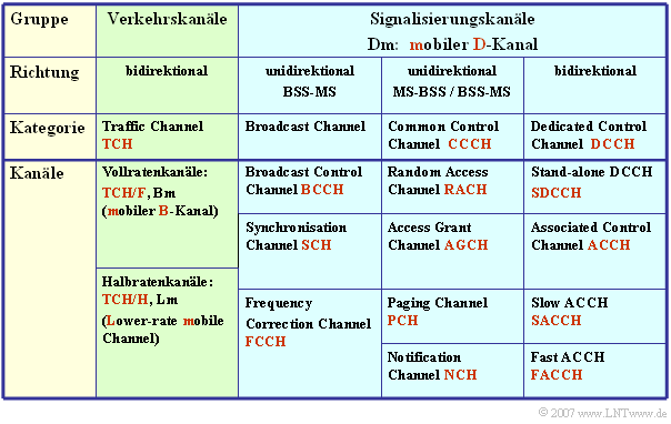
Let's start with the logical channels. These can occupy either an entire physical channel or only a portion of a physical channel and fall into two categories:
- Traffic Channels are used exclusively for the transmission of user data streams such as voice, fax and data. These channels are for both directions – so.
- Mobile Station (MS) ⇔ Base Station Subsystem (BSS)
- designed and can be occupied either by a full rate traffic channel $\text{(13 kbit/s)}$ or by two half rate channels $\text{(5.6 kbit/s each)}$ .
- Control Channels supply all active mobile stations via the radio interface by means of packet-oriented signaling in order to be able to receive messages from the Base Transceiver Station (BTS ) or send messages to the BTS at any time.
The table lists the logical channels of the GSM.
- These differ from the logical ISDN channels by an additional "m" for "mobile".
- For example, the "Bm channel" is comparable to the B channel of ISDN.
Uplink and downlink parameters
The logical channels are mapped to physical channels which describe all physical aspects of data transport:
- the frequency ranges for uplink (radio link mobile station → base station) and downlink (radio link base station → mobile station),
- the division between Time Division Multiple Access (TDMA) and Frequency Division Multiple Access (FDMA),
- the burst structure, i.e. the occupancy of a TDMA time slot in different applications (user and signaling data, synchronization marks, etc.),
- the modulation method Gaussian Minimum Shift Keying (GMSK), a variant of Continuous Phase - Frequency Shift Keying (CP-FSK) with large bandwidth efficiency.
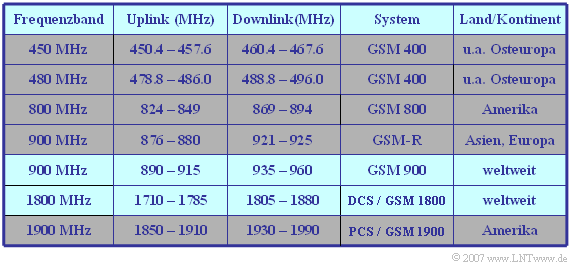
The following table shows the frequency ranges of the standardized GSM systems. To prevent intermodulation interference between the two directions, there is a guard band between the bands for uplink and downlink, the so-called duplex spacing.
$\text{Example 1:}$ With $\text{System GSM 900}$ (in Germany: D-Netz) the uplink starts at $\text{890 MHz}$ and the downlink at $\text{935 MHz}$.
- The duplex spacing is thus $\text{45 MHz}$.
- Both the uplink and the downlink have a bandwidth of $\text{25 MHz}$.
- After subtracting the guard bands at each of the two edges of $\text{100 kHz}$ there remain $\text{24.8 MHz}$, which are divided into $124$ FDMA channels of $\text{200 kHz}$ each.
The $\text{DCS band}$ (E–Netz) in the range around $\text{1800 MHz}$ has a duplex spacing of $\text{95 MHz}$ and a respective bandwidth of $\text{75 MHz}$.
- Taking into account the guard bands, this results in $374$ FDMA channels at $\text{200 kHz}$ each.
Realization of FDMA and TDMA
In the GSM system, two multiple access methods are used in parallel:
- Frequency Division Multiple Access (FDMA); and
- Time division multiple access (Time Division Multiple Access, TDMA).
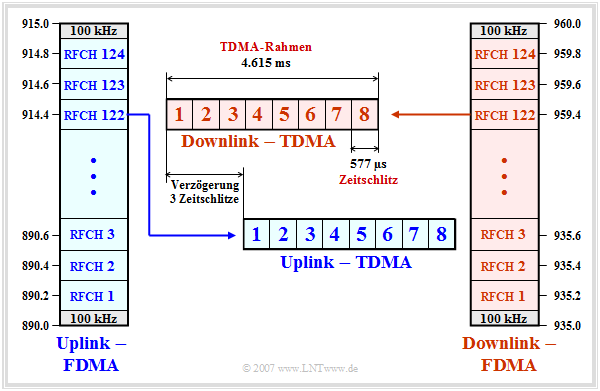
The graphic and the description apply to the $\text{GSM 900}$ system, known in Germany as D-Netz (D network).
Comparable statements apply to the other GSM systems.
We also refer here to the " GSM frame structure" and the "Exercise 3.3".
- In both the uplink and downlink, the transmission of signaling and traffic data occurs in parallel in $124$ frequency channels, designated "RFCH1" to "RFCH124".
- The center frequency of the uplink channel $n$ is at $890 \ {\rm MHz} + n - 0.2 \ {\rm MHz} \ \ ( n = 1$, ... , $124)$. At the upper and lower ends of the $25 \ {\rm MHz}$ band, there are guard bands of $100 \ {\rm kHz}$ each.
- The channel $n$ in the downlink is above the channel $n$ in the uplink at $935 \ {\rm MHz} + n - 0.2 \ {\rm MHz}$ by the duplex spacing of $45 \ {\rm MHz}$. The channels are designated in the same way as those in the uplink.
- Each cell is assigned some frequencies per Cell Allocation (CA). In adjacent cells one uses different frequencies. A subset of the CA is reserved for logical channels. The remaining channels are allocated to a mobile station as Mobile Allocation (MA).
- This is used, for example, for frequency hopping, where the data is sent over different frequency channels. This makes the transmission more stable against channel fluctuations. In most cases, frequency hopping is performed in packets.
- The individual GSM frequency channels are further subdivided by time division multiplexing (TDMA). Each FDMA channel is periodically divided into so-called TDMA frames which in turn each comprise eight time slots.
- The time slots (TDMA channels) are cyclically assigned to the individual subscribers and each contain a so-called burst of $156.25$ bit periods in length. Each GSM user has exactly one of the eight time slots available in each TDMA frame.
- The TDMA frames of the uplink are sent with three time slots delay compared to those of the downlink. This has the advantage that the same hardware of a mobile station can be used for both sending and receiving a message.
- The duration of a time slot is $T_{\rm Z} ≈ 577 \rm µ s$, that of a TDMA frame $4,615 \rm ms$. These values result from the GSM frame structure. In total $26$ TDMA frames are combined into a so-called multiframe of duration $120 \ \rm ms$ :
- $$T_{\rm Z} = \frac{120\,{\rm ms}}{8 \cdot 26} \approx 576.9\,{\rm µ s }\hspace{0.05cm}. $$
The different burst types in GSM
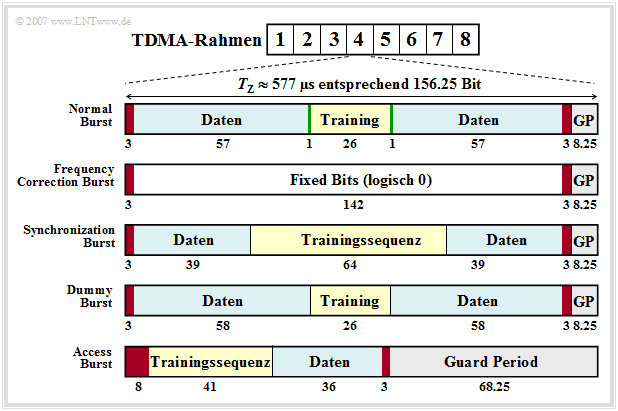
As just shown, a burst contains $156.25$ bits each and has duration $T_{\rm Z} ≈ 577 \rm µ s$.
- From this, the bit duration is calculated to $T_{\rm B} ≈ 3.69 \rm µ s$.
- To avoid overlapping of bursts due to different propagation times between mobile and base station, a Guard Period (GP) is inserted at the end of each burst.
- This guard period is $8.25$ bit durations, so $8.25 - 3.69 \ {\rm µ s} ≈ 30.5 \ {\rm µ s}$.
There are five different types of bursts, as shown in the figure above:
- Normal Burst (NB),
- Frequency Correction Burst (FB),
- Synchronization Burst (SB),
- Dummy Burst (DB),
- Access Burst (AB).
- The Normal Burst is used to transmit data from traffic and signaling channels. The error protection coded user data (blue, two times $57$ bits) together with three tail bits each (red, during this time the transmit power is regulated), two signaling bits (green) and $26$ bits for the training sequence (yellow, required for channel estimation and synchronization) result in a total of $148$ bits. Added to this is the Guard Period of $8.25$ bits (gray).
- The two (green) signaling bits - also called Stealing Flags - indicate whether the burst transports only user data or high-priority signaling information, which is always to be transmitted without delay. The training sequence can be used to estimate the channel, which is a prerequisite for applying an equalizer to reduce pulse interference.
- The Frequency Correction Burst' is used to frequency synchronize a mobile station. All bits except the tail bits and the guard period are here set to logical "$0$". The repeated broadcast of such a burst on the Frequency Correction Channel (FCCH) corresponds to an unmodulated carrier signal with frequency $f_{\rm T} + Δf_{\rm A}$ (carrier frequency + frequency deviation) (Günter: Frequenzhub -> Frequency deviation?). This value results from the fact that the modulation method "Gaussian Minimum Shift Keying" is a FSK special case.
- The Synchronization Burst'' is used to transmit information that helps a mobile station synchronize in time with the BTS. Besides a long midamble of $64$ bits, the Synchronization Burst contains the TDMA frame number and the Base Transceiver Station Identity Code (BSIC). When such a burst is repeatedly broadcast, it is referred to as the Synchronization Channel (SCH).
- The Dummy Burst (DB) is transmitted by each Base Transceiver Station (BTS) on a frequency specially allocated to it (Cell Allocation) when there are no other bursts to be transmitted. This ensures that a mobile station can always take power measurements.
- The Access Burst' is used for random multiple access on the Random Access Channel (RACH). To keep the probability of collisions on the RACH low, the Access Burst has a substantially longer Guard Period of $68.25$ bit durations than the other bursts.
GSM frame structure
The GSM frame structure is used to map logical channels to physical channels. Here a distinction is made between
- the mapping in frequency, based on Cell Allocation (CA), Mobile Allocation (MA), the TDMA frame number (FN) and the rules for the (optional) Frequency Hopping,
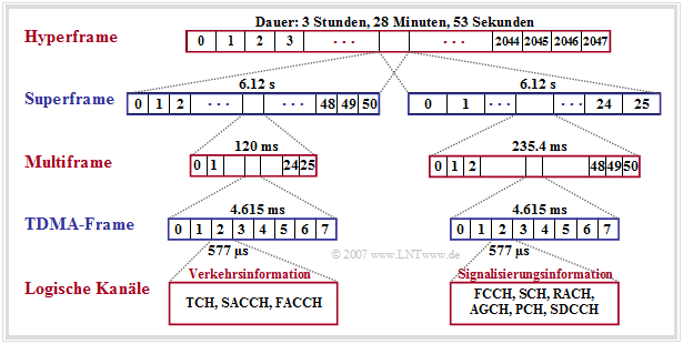
- mapping in time, where the TDMA frames are grouped into multiframes, superframes and hyperframes, each with eight time slots for transmitting the bursts.
According to this picture, the following statements are valid:
- Multiframes are used for mapping logical channels to physical channels. Two types can be distinguished here, those with $26$ TDMA frames and a cycle duration of $120 \ \rm ms$ and those with $51$ TDMA frames and a duration of $235.4 \ \rm ms$.
- The bursts of the traffic channels (TCH) and the associated control channels (SACCH, FACCH) are transmitted in $26$ successive TDMA frames each. Only one time slot per TDMA frame is always considered for the respective multiframe.
- Of the gross data rate per user $\text{(approx. 33.9 kbit/s)}$ are $\text{9.2 kbit/s}$ reserved for synchronization, signaling and Guard Period and $\text{1.9 kbit/s}$ for SACCH and IDLE. The (encoded and encrypted) user data occupy only $\text{22.8 kbit/s}$ for multiframe structure with $26$ frame.
- The multiframe structure with $51$ frames (right half of the picture) is used to multiplex several logical channels onto one physical channel. In 51 consecutive TDMA frames, all data of the signaling channels (except FACCH and SACCH) are transmitted respectively.
- One Superframe consists of $1326$ consecutive TDMA frames $(51$ multiframes with each $26$ TDMA frame or of $26$ multiframes with each $51$ TDMA frame$)$ and lasts approximately $6.12$ seconds.
- A hyperframe groups $2048$ superframes (or $2\hspace{0.08cm}715{\hspace0.08cm}648$ TDMA frames) together and is used with its long cycle duration to synchronize the payload encryption. This is $\text{3 hours, 28 minutes and 53,760 seconds}.$
Modulation in GSM systems
According to the statements of the last pages, $156.25$ bits per time slot $(0.5769 \ \rm ms)$ must be transmitted in one frequency channel. This corresponds to a total bit rate (for eight TDMA users including channel coding, signaling and synchronization information, etc.) of $R_{\rm ges} = 270\hspace{0.08cm}833 \rm bit/s$.
For this bit rate, a bandwidth of $B = 200 \ \rm kHz$ is available for GSM. Therefore, a modulation method with a bandwidth efficiency of at least $β =R_{\rm ges}/B = 1.35$ is required.
In GSM mobile radio, the modulation method Gaussian Minimum Shift Keying' (GMSK) is used. This has already been discussed in detail in the chapter "Nonlinear Digital Modulation" of the book "Modulation Methods". Here follows a brief, bullet-point description:
- GMSK is a modified form of Frequency Shift Keying' (FSK). This results from driving a "Frequency Modulator" with a binary bipolar rectangular input signal.
- Such an FSK signal $s(t)$ contains within each symbol duration $T$ only a single instantaneous frequency at a time $f_{\rm A}(t) = \rm const. $ If the (normalized) input signal is equal $+1$, then $f_{\rm A}(t)$ is equal to the sum of the carrier frequency $f_{\rm T}$ and the frequency deviation $Δf_{\rm A}$. Correspondingly, for the amplitude value $-1$: $f_{\rm A}(t) = f_{\rm T} - Δf_{\rm A}$.
- To allow easy demodulation, the two signals with frequencies $f_{\rm T} ± Δf$ should be orthogonal to each other within the symbol duration $T$ . Consequently, it must hold:
- $$\int^{T} _{0} \cos \big(2 \pi t \cdot (f_{\rm T}+ \Delta f_{\rm A} )\big)\cdot \cos \big(2 \pi t \cdot (f_{\rm T}- \Delta f_{\rm A} )\big)\,{\rm d}t= 0\hspace{0.05cm}. $$
- This results in the requirement for the frequency deviation :
- $$\Delta f_{\rm A} = \frac{k}{4 \cdot T}\hspace{0.2cm}{\rm with}\hspace{0.2cm}k = 1, 2, 3, \text{...}$$
- Since in FSK systems the modulation index' is defined to $h = 2 - Δf_{\rm A} - T$ is defined, it follows $h = k/2$. Thus, the smallest value satisfying the orthogonality conditions is $h_{\rm min} = 0.5$.
- An FSK system with $h = 0.5$ or $Δf_{\rm A}$ = ${1}/{4T}$ is called "Minimum Shift Keying" - MSK for short. This is used in all GSM systems, because a larger modulation index than $h = 0.5$ would require a significantly larger bandwidth.
- A very narrow spectrum results, however, only if phase jumps are avoided at the symbol boundaries by phase value matching. MSK thus belongs to the Continuous Phase Frequency Shift Keying techniques (CP-FSK, see next page).
- An additional low-pass filter with Gaussian characteristics is inserted before the frequency modulator, further reducing the GSM bandwidth. This type of modulation is called "Gaussian Minimum Shift Keying" ('GMSK).
Continuous phase adjustment with FSK
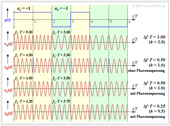
Ausgehend vom Rechtecksignal $q(t)$ und der Trägerfrequenz $f_{\rm T} = 4/T$ betrachten wir die FSK–Signale $s_{\rm A}(t)$, ... , $s_{\rm D}(t)$ bei unterschiedlichem Frequenzhub $Δf_{\rm A}$ ⇒ Modulationindex $h = 2 · Δf_{\rm A} · T$.
Zu den Signalverläufen ist anzumerken (wir verweisen auch auf das interaktive Applet Frequency Shift Keying & Continuous Phase Modulation):
- Das Signal $s_{\rm A}(t)$ ergibt sich mit $Δf_{\rm A} = 1/T$ ⇒ Modulationsindex $h = 2$. Man erkennt die höhere Frequenz $f_1 = 5/T$ $($für $a_ν = +1)$ gegenüber der Frequenz $f_2 = 3/T$ $($für $a_ν = -1)$.
- Mit $Δf_{\rm A} = 0.5/T$ $($Signal $s_{\rm {\rm B}}(t)$, $h = 1)$ gilt $f_1 = 4.5/T$ und $f_2 = 3.5/T$. An jeder Symbolgrenze tritt ein Phasensprung um $π$ auf, wenn keine Phasenanpassung wie beim Signal $s_{\rm C}(t)$ vorgenommen wird.
- Bei $s_{\rm C}(t)$ wird im Bereich $0$ ... $T$ der Koeffizient $a_1 = +1$ durch $\cos(2π·f_1·t)$ repräsentiert, während der ebenfalls positive Koeffizient $a_2 = +1$ im Bereich $T$ ... $2T$ zum Signal $-\cos(2π·f_1\hspace{0.01cm}·\hspace{0.01cm}(t-T))$ führt. Durch diese Anpassung werden somit Phasensprünge vermieden.
- Das Signal $s_{\rm D}(t)$ beschreibt das MSK-Signal $($Frequenzhub $Δf_{\rm A} = 0.25/T$ ⇒ Modulationsindex $h = 0.5)$, ebenfalls mit Phasenanpassung. Hier sind bei jeder Symbolgrenze – je nach den vorherigen Symbolen – vier unterschiedliche Anfangsphasen möglich.
- Bei $\rm GSM \ 900$ beträgt die Trägerfrequenz $f_{\rm T} = 900\ \rm MHz$ und die Symboldauer ist $T ≈ 3.7 \ \rm µ s$. Mit dem Modulationsindex $h = 0.5$ ergibt sich $Δf_{\rm A} ≈ 68 \ \rm kHz$. Die beiden Frequenzen $f_1 = 900.068\ \rm MHz$ und $f_2 = 899.932 \ \rm MHz$ liegen somit sehr eng beieinander.
Minimum Shift Keying (MSK)
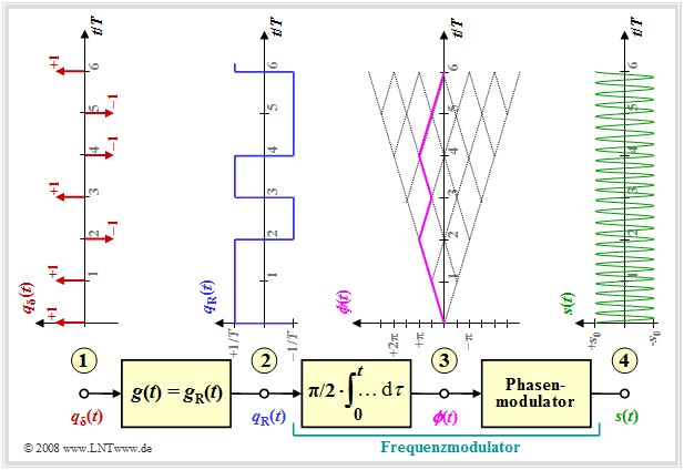
Die Grafik zeigt das Modell zur Erzeugung einer MSK–Modulation und typische Signalverläufe.
Man erkennt
- am Punkt (1) das digitale Quellensignal, bestehend aus einer Folge von Diracimpulsen im Abstand $T$, gewichtet mit den Amplitudenkoeffizienten $a_ν ∈ \{-1, +1\}$:
- $$q_\delta(t) = \sum_{\nu = - \infty}^{+\infty}a_{ \nu} \cdot \delta (t - \nu \cdot T)\hspace{0.05cm}; $$
- am Punkt (2) das Rechtecksignal $q_{\rm R}(t)$ nach Faltung mit dem Rechteckimpuls $g(t)$ der Dauer $T$ und der Höhe $1/T$ (die Amplitude wurde aus Kompatibilitätsgründen zu späteren Seiten so gewählt):
- $$q_{\rm R}(t) = \sum_{\nu = - \infty}^{+\infty}a_{ \nu} \cdot g (t - \nu \cdot T)\hspace{0.05cm}; $$
- den Frequenzmodulator, der sich gemäß der Beschreibung im Kapitel Signalverläufe bei FM als Integrator und nachgeschalteten Phasenmodulator realisieren lässt. Für das Signal am Punkt (3) gilt dann:
- $$\phi(t) = \frac{\pi}{2}\cdot \int_{0}^{t} q_{\rm R}(\tau)\hspace{0.1cm} {\rm d}\tau \hspace{0.05cm}.$$
Die Phasenwerte bei der Symboldauer $T$ sind Vielfache von $π/2 \ (90^\circ)$, wobei der für MSK gültige Modulationsindex $h = 0.5$ berücksichtigt ist. Der Phasenverlauf ist linear. Daraus ergibt sich am Punkt (4) des Blockschaltbildes das MSK–Signal zu
- $$s(t) = s_0 \cdot \cos \big(2 \pi f_{\rm T} \hspace{0.05cm}t + \phi(t)\big) = s_0 \cdot \cos \big(2 \pi \cdot t \cdot (f_{\rm T}+a_{ \nu} \cdot {\rm \Delta}f_{\rm A} )\big) \hspace{0.05cm}.$$
Die Realisierung von Minimum Shift Keying (MSK) durch eine spezielle Variante von Offset–QPSK wird durch das interaktive Applet QPSK und Offset–QPSK verdeutlicht.
Gaussian Minimum Shift Keying (GMSK)
Ein Vorteil von MSK gegenüber anderen Modulationsarten ist der geringere Bandbreitenbedarf. Durch geringfügige Modifikationen hin zum Gaussian Minimum Shift Keying – abgekürzt GMSK– ergibt sich nochmals eine schmaleres Spektrum.
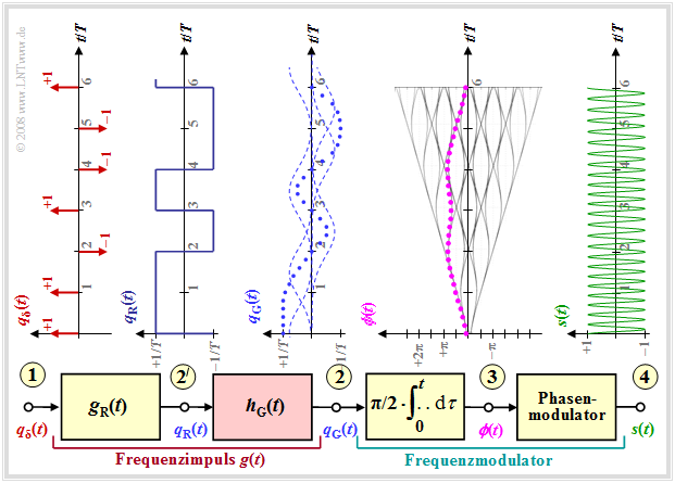
Man erkennt aus dem Blockschaltbild folgende Unterschiede zum MSK (wir verweisen auf das interaktive Applet Frequency Shift Keying & Continuous Phase Modulation):
- Der Frequenzimpuls $g(t)$ ist nun nicht mehr rechteckförmig wie der Impuls $g_{\rm R}(t)$, sondern weist flachere Flanken auf. Demzufolge ergibt sich auch ein weicherer Phasenverlauf am Punkt (3) als beim MSK–Verfahren (siehe letzte Seite), bei dem $ϕ(t)$ symbolweise linear ansteigt bzw. abfällt.
- Man erreicht diese sanfteren Phasenübergänge bei GMSK durch ein Gaußtiefpassfilter mit dem Frequenzgang bzw. der Impulsantwort
- $$H_{\rm G}(f) = {\rm e}^{-\pi \hspace{0.05cm} \cdot \hspace{0.05cm} \big({f}/(2 \hspace{0.05cm} \cdot \hspace{0.05cm} f_{\rm G})\big)^2} \hspace{0.2cm}\bullet\!\!-\!\!\!-\!\!\!-\!\!\circ\, \hspace{0.2cm} h_{\rm G}(t) = 2 f_{\rm G} \cdot {\rm e}^{-\pi\hspace{0.05cm} \cdot \hspace{0.05cm} (2 \hspace{0.05cm} \cdot \hspace{0.05cm} f_{\rm G}\hspace{0.05cm} \cdot \hspace{0.05cm} t)^2}\hspace{0.05cm}.$$
- Bei GSM ist die 3dB–Grenzfrequenz zu $f_{\rm 3dB} = 0.3/T$ festgelegt. Wie in Aufgabe Aufgabe 3.4 gezeigt wird, gilt somit für die systemtheoretische Grenzfrequenz:
- $$f_{\rm G} ≈ 1.5 · f_{\rm 3dB} = 0.45/T.$$
- Der resultierende Frequenzimpuls $g(t)$ am Punkt (2) des Blockschaltbildes ergibt sich aus der Faltung des Rechteckimpulses $g_{\rm R}(t)$ mit der Impulsantwort $h_{\rm G}(t)$ des Gaußtiefpasses zu
- $$g(t) = g_{\rm R}(t) \star h_{\rm G}(t)\hspace{0.05cm}. $$
- Das GMSK–modulierte Signal $s(t)$ weist nun nicht mehr abschnittsweise (je Symboldauer) eine konstante Frequenz auf.
Diesen Unterschied zur MSK kann man allerdings aus dem Signalverlauf am Punkt (4) des Blockschaltbildes nur schwer erkennen.
Advantages and disadvantages of GMSK
Hier werden die wichtigsten Merkmale des Modulationsverfahren Gaussian Minimum Shift Keying zusammenfassend aufgeführt.
$\text{Fazit:}$ Der wesentliche Vorteil von GMSK ist der sehr geringe Bandbreitenbedarf.
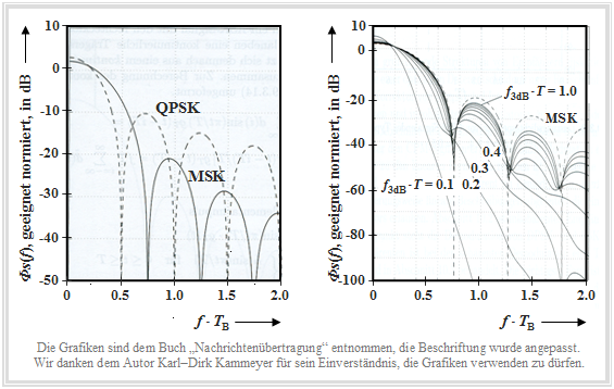
Die folgende Grafik wurde dem Buch [Kam04][1] entnommen.
- Die linke Grafik zeigt das logarithmierte Leistungsdichtespektrum $10 · \text{lg} \ {\it Φ}_s(f)/{\it Φ}_0$ des Verfahrens Minimum Shift Keying (MSK) im Vergleich zu Quaternary Phase Shift Keying (QPSK), wobei ${\it Φ}_0$ „geeignet” gewählt wurde.
- Auf der Abszisse ist die normierte Frequenz $f · T_{\rm B}$ aufgetragen. Bei MSK ist die Bitdauer $T_{\rm B}$ gleich der Symboldauer $T$, während bei QPSK $T_{\rm B} = T/2$ gilt.
- Im rechten Diagramm, das sich ausschließlich auf (G)MSK bezieht, könnte die Abszisse auch mit $f · T$ beschriftet werden.
Man erkennt aus der linken Darstellung:
- Die erste Nullstelle im Leistungsdichtespektrum (LDS) tritt bei der QPSK (gestrichelte Kurve) beim normierten Abszissenwert $f · T_{\rm B} = 0.5$ auf, bei der MSK dagegen erst bei $f · T_{\rm B} = 0.75$.
- Im weiteren Verlauf ergibt sich jedoch bei MSK ein deutlich schnellerer LDS–Abfall als der asymptotische $f^{-2}$–Abfall bei QPSK.
- Zu beachten ist, dass für die MSK ein Cosinusimpuls zur Spektralformung zugrunde liegt und für die QPSK ein Rechteckimpuls.
Die rechte Darstellung zeigt den Einfluss der gaußförmigen Impulsformung bei GMSK auf das Leistungsdichtespektrum ${\it Φ}_s(f)$, wobei als Parameter die normierte 3dB–Grenzfrequenz verwendet wird.
- Je kleiner $f_{\rm 3\ dB}$ ist, desto schmalbandiger ist das Leistungsdichtespektrum. Im GSM–Standard wurde $f_{\rm 3\ dB} · T$ = 0.3 festgelegt. Mit diesem Wert wird die Bandbreite bereits entscheidend reduziert, was zu geringeren Nachbarkanalinterferenzen führt.
- Andererseits wirken sich mit dieser Grenzfrequenz die Impulsinterferenzen schon gravierend aus. Die Augenöffnung ist kleiner als $50\%$ und es ist eine geeignete Entzerrung vorzusehen.
Des Weiteren ist zu vermerken:
- Die binäre FSK stellt – auch bei kontinuierlicher Phasenanpassung – allgemein ein nichtlineares Modulationsverfahren dar. Deshalb ist eine kohärente Demodulation eigentlich nicht möglich.
- Eine Ausnahme bildet die MSK als Sonderfall für den Modulationsindex $h = 0.5$, die sich als Offset–QPSK linear realisieren lässt und somit auch kohärent demoduliert werden kann.
- Ohne Berücksichtigung der Impulsinterferenzen beträgt die Bitfehlerwahrscheinlichkeit
- $$p_{\rm B} = {\rm Q} \left(\sqrt{{E_{\rm B}}/{N_0}}\hspace{0.09cm}\right) = {1}/{2}\cdot{\rm erfc} \left(\sqrt{{E_{\rm B}}/{2N_0}}\hspace{0.09cm}\right) \hspace{0.05cm}.$$
- Gegenüber der QPSK ergibt sich eine Degradation um $3\ \rm dB$. Das interaktive Applet Komplementäre Gaußsche Fehlerfunktionen liefert die Zahlenwerte der hier verwendeten Funktionen ${\rm Q}(x)$ bzw. $1/2 \cdot {\rm erfc}(x)$.
- Ein Vorteil der GMSK gegenüber der QPSK ist, dass sich trotz der spektralen Formung des Grundimpulses eine konstante Hüllkurve ergibt. Deshalb spielen Nichtlinearitäten auf dem Kanal nicht eine so große Rolle als bei anderen Modulationsverfahren. Dies ermöglicht den Einsatz einfacher und kostengünstiger Leistungsverstärker, einen geringeren Leistungsverbrauch und damit auch längere Betriebsdauern akkubetriebener Geräte.
Radio Subsystem Link Control
Eine weitere Funktion der Funkschnittstelle ist die Steuerung der Funkverbindung. So übernimmt das so genannte Radio Subsystem Link Control folgende Aufgaben:
Es ist für die Messung der Empfangsqualität zuständig. Während einer aufgebauten Verkehrs– oder Signalisierungsverbindung erfolgt in regelmäßigen Abständen die Kanalvermessung der Mobilstation hinsichtlich Empfangsfeldstärke und Bitfehlerrate ⇒ Quality Monitoring. Diese Werte werden in einem Messreport zur Basisstation über den Signalisierungskanal SACCH übertragen und von dieser für die Leistungsregelung und das Handover verwendet.
Die Power Control (deutsch: Leistungsregelung) ist erforderlich, damit alle Mobilstationen nur mit der minimal erforderlichen Energie abstrahlen. Die Sendeleistung kann adaptiv in Schritten von $2 \ \rm dBm$ zwischen $43 \ \rm dBm$ $\text{(Stufe 0:}$ $20\ \rm W$) und $13 \ \rm dBm$ $\text{(Stufe 15:}$ $20\ \rm mW$) geregelt werden. Auch die Sendeleistung der Basisstationen wird in Schritten von $2 \ \rm dBm$ angepasst, um optimale Netzkapazität zu erzielen. Eine Ausnahme bildet der BCCH–Träger mit konstanter Sendeleistung, um den Mobilstationen eine vergleichende Messung benachbarter BCCH–Träger zu ermöglichen.
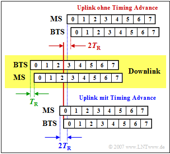
Das Adaptive Frame Alignment – also die adaptive Rahmensynchronisation – dient dazu, Kollisionen zwischen Uplink– und Downlinkdaten zu vermeiden, die von der Mobilstation um drei Zeitschlitze versetzt gesendet bzw. empfangen werden sollen. Dies zeigt nebenstehende Grafik.
Im mittleren, gelb hinterlegten Bereich ist der Downlink dargestellt, wobei die Daten um die Zeit $T_{\rm R}$ (Round Trip Delay Time) später bei der Mobilstation (MS) ankommen, als sie von der Base Transceiver Station (BTS) gesendet wurden (grüne Markierung).
Im oberen Bereich ist der Uplink ohne Timing Advance dargestellt.
- Die MS beginnt genau drei Zeitschlitze nach dem Empfang mit dem Senden (blaue Markierung).
- Aufgrund der Verzögerungen im Downlink und Uplink erreicht der Zeitschlitz $0$ die BTS nicht wie gefordert zu der Zeit $3T_{\rm Z}$, sondern um $2T_{\rm Z}$ später (rote Markierung).
- Beim Timing Advance Uplink (untere Skizze) wird diese Verzögerung bereits von der Mobilstation kompensiert, indem die Daten um die Zeit $T_{\rm A} = 2T_{\rm R}$ früher versandt werden und diese somit genau zeitsynchron bei der BTS ankommen.
Für das Timing Advance stehen die Stufen $0 – 63$ zur Verfügung, wobei jede Stufe einer Bitdauer $T_{\rm B}$ entspricht.
- Das maximale Timing Advance beträgt somit $\rm 63 · 3.7 \ µ s ≈ 233 \ µs$, so dass sich die maximale zulässige Laufzeit in einer Richtung zu $T_{\rm R} ≈ 116\ {\rm µ s}$ ergibt.
- Daraus kann der erlaubte Zellenradius von GSM (Entfernung zwischen BTS und MS) berechnet werden:
- $$116\ \rm µ s · 3 · 10^8 \ m/s ≈ 35 \ km.$$
Aufgaben zum Kapitel
Aufgabe 3.3: GSM–Rahmenstruktur
Aufgabe 3.3Z: GSM 900 und GSM 1800
Aufgabe 3.4Z: FSK mit kontinuierlicher Phase
Quellenverzeichnis
- ↑ Kammeyer, K.D.: Nachrichtenübertragung. Stuttgart: B.G. Teubner, 4. Auflage, 2004.
