System Components of a Baseband Transmission System
- [[Digital Signal Transmission/{{{Vorherige Seite}}} | Previous page]]
- [[Digital Signal Transmission/{{{Vorherige Seite}}} | Previous page]]
Contents
- 1 # OVERVIEW OF THE FIRST MAIN CHAPTER #
- 2 Simplified system model
- 3 Descriptive variables of the digital source
- 4 Characteristics of the digital transmitter
- 5 Transmission channel and interference
- 6 Receiver filter and threshold decision
- 7 Block diagram and prerequisites for the first main chapter
- 8 Exercises for the chapter
- 9 References
# OVERVIEW OF THE FIRST MAIN CHAPTER #
The first main chapter introduces the broad field of digital signal transmission, with some simplifying assumptions: a redundancy-free binary transmitted signal, no intersymbol interference. Although the description is mainly in baseband, most of the results can be applied to the digital carrier frequency systems as well.
In particular, the following are dealt with:
- The »basic structure and components« of a baseband transmission system,
- the definitions of »bit error probability« and »bit error rate«,
- the characteristics of »Nyquist systems« that allow intersymbol interference-free transmission,
- the »optimization of the binary baseband systems« under power and peak constraints,
- the generalization of the results to »carrier frequency systems«, and
- the largely common description of »ASK, BPSK, and 4-QAM«.
Simplified system model
Throughout the first chapter, the following block diagram is assumed for the digital system as described in [TS87][1]:
The block diagram is constructed in exactly the same way as an "analog transmission system" according to the description in the book "Modulation Methods", consisting of
- source ⇒ German: "Quelle", marking: "Q",
- transmitter ⇒ German: "Sender", marking: "S",
- channel ⇒ German: "Kanal", marking: "K",
- interference/noise ⇒ German: "Störung", marking: "N",
- receiver ⇒ German: "Empfänger", marking: "E",
- sink ⇒ German: "Sinke", marking: "V".
The corresponding signals are adapted to these labels, but use lower case letters, e.g. source signal $q(t)$, ... , sink signal $v(t)$.
In comparison to an analog transmission system, the following similarities and differences can be recognized in this simplified system model:
- Also in the digital transmission system, the received signal $r(t)$ is continuous in time and value due to stochastic effects, e.g. noise. The transmitted signal $s(t)$ can be discrete in time and value, but does not have to be.
- In contrast to the book "Modulation Methods", however, the source signal $q(t)$ and the sink signal $v(t)$ are always digital signals. Accordingly, they are both discrete-time and discrete-value.
- All information about $q(t)$ and $v(t)$ can thus also be expressed by the "source symbol sequence" $〈q_ν〉$ and the "sink symbol sequence" $〈v_ν〉$ together with the symbol duration $T$.
- A digital receiver differs fundamentally from the receiver of an analog system in that it must also include a decision component for obtaining the digital sink signal $v(t)$ from the analog received signal $r(t)$.
- In the first three chapters of this book, we consider digital baseband transmission, which means that the signal $q(t)$ is transmitted without prior frequency conversion (modulation with a carrier wave).
- Therefore, $s(t)$ and $r(t)$ are low-pass signals here, and the channel (including interferences) must always be assumed to have low-pass characteristics as well.
In the following, the characteristics of the individual system components are described in detail, suitably considering the idealizing assumptions for this chapter.
Descriptive variables of the digital source
The digital source generates the source symbol sequence $〈q_ν〉$, which is to be transmitted to the sink as error-free as possible. In general, each symbol of the temporal sequence $〈q_ν〉$ with $\nu = 1, 2,$ ... from a symbol set $\{q_\mu\}$ with $\mu = 1$, ... , $M$, where $M$ is called the "source symbol set size" or the "level number".
For the present first main chapter of this book, the following assumptions are made:
- The source is "binary" $(\hspace{-0.05cm}M= 2)$ and the two possible symbols are $\rm L$ ("Low") and $\rm H$ ("High"). We have chosen this somewhat unusual nomenclature in order to be able to describe both unipolar and bipolar signaling in the same way. Please see the note before $\text{Example 1}$.
- The source symbols are "statistically independent", that is, the probability ${\rm Pr}(q_\nu = q_\mu)$, that the $\nu$–th symbol of the sequence $〈q_ν〉$ is equal to the $\mu$–th symbol of the symbol set $\{q_\mu\}$ does not depend on $\nu$.
- Given these two assumptions, the digital source is completely described by the "'symbol probabilities" $p_{\rm L} = {\rm Pr}(q_\nu = {\rm L}) $ and $p_{\rm H} = {\rm Pr}(q_\nu = {\rm H}) = 1- p_{\rm L}$. If $p_{\rm L} =p_{\rm H}= 0.5$ is still valid, the source is "redundancy-free". Mostly – but not always – such a redundancy-free binary source is assumed in the present first chapter.
- Let the time interval between two symbols be $T$. This quantity is called the "symbol duration" and the reciprocal value is the "symbol rate" $R = 1/T$. For binary sources $(\hspace{-0.05cm}M= 2)$ these quantities are also called "bit duration" and "bit rate", resp.
- With a system-theoretical view to digital baseband transmission, the source signal is best described by a sequence of weighted and shifted Dirac delta impulses:
- \[q(t) = \sum_{(\nu)} a_\nu \cdot {\rm \delta} ( t - \nu \cdot T)\hspace{0.05cm}. \]
- Here, we refer to $a_\nu$ as the amplitude coefficients. In the case of "binary unipolar" digital signal transmission:
- \[a_\nu = \left\{ \begin{array}{c} 1 \\ 0 \\ \end{array} \right.\quad \begin{array}{*{1}c} {\rm{for}} \\ {\rm{for}} \\ \end{array}\begin{array}{*{20}c} q_\nu = \mathbf{H} \hspace{0.05cm}, \\ q_\nu = \mathbf{L} \hspace{0.05cm}. \\ \end{array}\]
- Correspondingly, in the case of a "binary bipolar" system:
- \[a_\nu = \left\{ \begin{array}{c} +1 \\ -1 \\ \end{array} \right.\quad \begin{array}{*{1}c} {\rm{for}} \\ {\rm{for}} \\ \end{array}\begin{array}{*{20}c} q_\nu = \mathbf{H} \hspace{0.05cm}, \\ q_\nu = \mathbf{L} \hspace{0.05cm}. \\ \end{array}\]
- The following description is mostly for this second case.
$\text{Note on nomenclature:}$
- In the literature, our symbol $\rm H$ is often denoted by $\mathbf{0}$.
- In unipolar signaling, the symbol $\mathbf{0}$ is then represented by the amplitude coefficient $a_\nu =1$ and the symbol $\rm L$ by the numerical value $a_\nu =0$.
- To avoid this unattractive situation in our "LNTwww", the symbol $\mathbf{1}$ is denoted by $\rm H$, where "High" expresses the situation correctly.
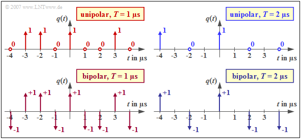
$\text{Example 1:}$ The graphic shows four binary Dirac-shaped source signals in the range from $-4 \ \rm µ s$ to $+4 \ \rm µ s$, each based on the source symbol sequence
- $$\langle q_\nu \rangle = \langle \text{...}\hspace{0.05cm}, \mathbf{L}, \mathbf{H}, \mathbf{H}, \mathbf{L},\hspace{0.15cm}\mathbf{H}, \hspace{0.15cm} \mathbf{L},\mathbf{L}, \mathbf{H},\mathbf{L},\hspace{0.05cm} \text{...} \rangle \hspace{0.05cm} $$
The middle symbol $($marked in the equation by larger character spacing$)$ refers in each case to the time $t = 0$.
- The two upper signals are suitable for describing unipolar systems, the lower ones for bipolar (antipodal) digital signal transmission.
- For the diagrams on the left, $T = 1\ \rm µ s$ is assumed. For the two right ones, however, $T = 2\ \rm µ s$ and thus half the symbol rate applies.
Characteristics of the digital transmitter
The transmitter of a digital transmission system has the task of generating a suitable transmitted signal $s(t)$ from the (Dirac-shaped) source signal, which contains the message of the source completely and is adapted to the characteristics of the transmission channel, the interferences as well as all technical receiving equipment. In addition, the transmitter ensures the provision of a sufficiently large transmission power.
As a descriptive quantity for the transmitter, we use the basic transmitter pulse $g_s(t)$. Due to the definition of the source signal $q(t)$ as a sum of weighted and shifted Dirac delta functions, the transmitted signal can be represented with the amplitude coefficients $a_\nu$ in the following way:
- \[s(t) = q(t) \star g_s(t) = \sum_{(\nu)} a_\nu \cdot g_s ( t - \nu \cdot T)\hspace{0.05cm}.\]
Often the basic transmitter pulse $g_s(t)$ is assumed to be rectangular with
- the pulse height $s_0 = g_s(t = 0)$ and
- the (absolute) pulse duration $T_{\rm S}$.
$\text{Definition:}$ If $T_{\rm S} < T$ applies, this is referred to as an RZ pulse ("return–to–zero"), and if $T_{\rm S} = T$, this is referred to as an NRZ pulse ("non–return–to–zero").
With a different basic transmitter pulse, for example
the "equivalent pulse duration" defined by the equal-area rectangle is usually used as description parameter instead of the absolute pulse duration $T_{\rm S}$:
- $$\Delta t_{\rm S} = \frac {\int ^{+\infty} _{-\infty} \hspace{0.15cm} g_s(t)\,{\rm d}t}{{\rm Max} \hspace{0.05cm}[g_s(t)]} \le T_{\rm S} \hspace{0.05cm}.$$
Only in case of the rectangular basic transmitter pulse $\Delta t_{\rm S} = T_{\rm S}$ is valid.
If the height of the basic transmitter pulse $g_s(t)$ differs from the maximum value $s_0$ of the transmitted signal $s(t)$, we denote the pulse amplitude by $A_{\rm S}$. This is true for the Gaussian pulse, for example.
The interaction module "Pulses and Spectra" shows some common basic transmitter pulses $g_s(t)$ and the corresponding spectra $G_s(f)$.
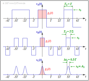
$\text{Example 2:}$ The following graphic is always based on the source symbol sequence $\langle q_\nu \rangle = \langle \text{...}\hspace{0.05cm}, \mathbf{L}, \mathbf{H}, \mathbf{H}, \mathbf{L},\hspace{0.15cm}\mathbf{H}, \hspace{0.15cm}\mathbf{L},\mathbf{L}, \mathbf{H},\mathbf{L},\hspace{0.05cm} \text{...} \rangle $. It shows three transmitted signals,
- a bipolar transmitted signal $s_{\rm A}(t)$ with NRZ rectangular pulses,
- a bipolar transmitted signal $s_{\rm B}(t)$ with RZ rectangular pulses, and
- a unipolar transmitted signal $s_{\rm C}(t)$ with Gaussian pulses.
In the following descriptions, the bipolar NRZ rectangular ("square-wave") signal $s_{\rm A}(t)$ is usually assumed. The duration $T_{\rm S}$ of the basic transmitter pulse $g_s(t)$ shown in red in the diagram is equal to the distance $T$ between two successive pulses.
From the additional diagrams one recognizes:
- For the RZ transmitted signal $s_{\rm B}(t)$, the pulse duration $T_{\rm S}$ differs from the pulse spacing $T$. The diagram applies to the duty cycle $T_{\rm S}/T = 0.5$. Although $s_{\rm B}(t)$ is also a binary signal, there are three possible signal values here, namely $+s_0$, $-s_0$ and $0$.
- An advantage is that even with a long $\rm H$ or $\rm L$ sequence there is no DC signal, which makes clock synchronization easier. A disadvantage of RZ signaling is the wider spectrum as well as the lower energy per symbol, which leads to a higher bit error rate.
- The signal $s_{\rm C}(t)$ is unipolar and uses a Gaussian basic pulse $g_s(t)$. Such a signal is found, for example, in optical systems with intensity modulation, since a laser or an LED ("Light Emitting Diode") cannot generate negative pulses in principle and a rectangular pulse is technologically more difficult to achieve than the Gaussian form.
- In case of a "real Gaussian pulse" the absolute pulse duration is always $T_{\rm S} \to \infty$. The (normalized) equivalent pulse duration is chosen here with $\Delta t_{\rm S} /T = 0.3$ relatively small, so that the maximum value $s_0$ of the transmitted signal is approximately equal to the pulse amplitude $A_{\rm S}$.
- For wider Gaussian pulses these overlap; the approximation $s_0 \approx A_{\rm S}$ no longer applies in this case.
Transmission channel and interference
The transmission channel includes all the equipment located between the transmitter and the receiver. The main component of the channel is the transmission medium, which can be, for example,
- a symmetrical double line,
- a coaxial cable,
- an optical fiber ("glass fiber"), or
- a radio field.
In addition, the transmission channel includes various equipment necessary for operational reasons, such as power supply, lightning protection and fault location.
In the most general case, the following physical effects must be taken into account:
- The transmission characteristics may be "time-dependent", especially in the case of a moving transmitter and/or receiver, as described in detail in the first main chapter "Time-Variant Transmission Channels" of the book "Mobile Communications". In this book, the channel is always assumed to be linear and time-invariant $\rm (LTI)$.
- The characteristics of the LTI channel can be frequency dependent, characterized by the frequency response $H_{\rm K}(f)$. In conducted transmission, $H_{\rm K}(f) \ne \rm const.$ always holds and distortion occurs, as discussed in the section "Definition of the term Intersymbol Interference".
- Stochastic interference $n(t)$ is superimposed on the deterministic signal, for example the unavoidable thermal noise, pulse interference, and crosstalk interference from other subscribers.
For this first main chapter, $H_{\rm K}(f) =1$ is always assumed, which means that the first two points mentioned are excluded for the time being.
Thus, in the following, for the signal at the channel output always holds:
- $$r(t) = s(t) + n(t).$$
The simplest realistic assumption for the transmission channel of a communication system is Additive White Gaussian Noise $\rm (AWGN)$, as already stated in other LNTwww books,
- in the book "Theory of Stochastic Signals",
- in the section "Quality Criteria" in "Modulation Methods".
$\text{The AWGN channel model can be summarized as follows:}$
- The letter $\rm N$ indicates that only noise is considered by the AWGN model. Distortions of the useful signal $s(t)$ are not accounted for by this simple model.
- Although noise is generally caused by a variety of noise sources along the entire transmission path, for linear systems it can be accounted for by a single additive noise term at the channel output $($letter $\rm A)$.
- The noise includes all frequencies equally. It has a constant white $\rm (W)$ "power-spectral density" $\rm (PSD)$ and a Dirac-shaped "auto-correlation function" $\rm (ACF)$:
- $${\it \Phi}_n(f) = {N_0}/{2}\hspace{0.15cm} \bullet\!\!-\!\!\!-\!\!\!-\!\!\circ\, \hspace{0.15cm} \varphi_n(\tau) = {N_0}/{2} \cdot \delta (\tau)\hspace{0.05cm}.$$
- The factor $1/2$ on both sides of this Fourier transform equation accounts for the two-sided spectral representation.
- For example, in the case of thermal noise, for the physical noise power density $($that is: one-sided view) with noise figure $F \ge 1$ and absolute temperature $\theta$:
- \[{N_0}= F \cdot k_{\rm B} \cdot \theta , \hspace{0.3cm}k_{\rm B} = 1.38 \cdot 10^{-23} \hspace{0.2cm}{ \rm Ws}/{\rm K}\hspace{0.2cm}{\text{(Boltzmann constant)} }\hspace{0.05cm}.\]
- True white noise would result in infinitely large power. Therefore, a band limit on $B$ must always be considered. The following applies to the effective noise power:
- \[N = \sigma_n^2 = {N_0} \cdot B \hspace{0.05cm}.\]
- The noise signal $n(t)$ has a "Gaussian probability density function" $\rm (PDF)$, which is expressed by the letter $\rm G$:
- \[f_n(n) = \frac{1}{\sqrt{2\pi}\cdot\sigma_n}\cdot {\rm e}^{ - {\it n^{\rm 2} }/{(2\sigma_n^2)} }.\]
We would like to refer you here to the (German language) three-part learning video "AWGN Channel", in which the AWGN properties are clarified again.
Receiver filter and threshold decision
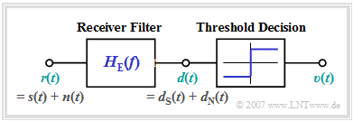
The simplest receiver for binary transmission via the AWGN channel consists of
- a receiver filter (German: "Empfangsfilter" ⇒ subscript: "E") with frequency response $H_{\rm E}(f)$,
- and a threshold decision for obtaining the binary signal.
This receiver structure can be justified as follows: The signal $d(t)$ after the receiver filter ⇒ "detection signal" can be divided at least mentally in two parts:
- $$d(t) = d_{\rm S}(t)+d_{\rm N}(t).$$
- The portion $d_{\rm S}(t)$ is due solely to the receiver input signal $r(t)=s(t)$ ⇒ $n(t)= 0$. The subscript "S" stands for "signal". In the following, we also refer to $d_{\rm S}(t)$ as the "signal component" of $d(t)$.
- With the impulse response $h_{\rm E}(t)$ as the Fourier retransform of the frequency response $H_{\rm E}(f)$ holds:
- $$d_{\rm S}(t) = s(t) \star h_{\rm E} (t)\hspace{0.05cm}.$$
- For the second part $d_{\rm N}(t)$, on the other hand, one assumes the receiver input signal $r(t)=n(t)$ ⇒ $s(t)= 0$.
We also refer to this portion $d_{\rm N}(t)$ as the "noise component" of $d(t)$. The following convolution operation applies to it:
- $$d_{\rm N}(t) = n(t) \star h_{\rm E} (t)\hspace{0.05cm}.$$
- The white noise $n(t)$ at the receiver input has theoretically an infinitely large power $($practically: an unnecessarily large power$)$. The low-pass filter with frequency response $H_{\rm E}(f)$ limits this to the squared expected value of the "noise component" $d_{\rm N}(t)$ ⇒ "variance" ⇒ "noise power":
- \[\sigma_d^2 = {\rm E}\big[d_{\rm N}(t)^2\big] \hspace{0.05cm}.\]
- However, it should be noted that the low-pass $H_{\rm E}(f)$ alters not only the noise $n(t)$, but also the transmitted signal $s(t)$. As a result, the individual transmission pulses are broadened and reduced in amplitude. According to the prerequisites for this chapter, it must be ensured that "intersymbol interference" does not occur.
- The decider's task is to generate the discrete–value and discrete–time sink signal $v(t)$ from the continuous–value and continuous–time detection signal $d(t)$, which should reproduce the message of the transmitted signal $s(t)$ as well as possible. The operation of the (binary) threshold decision is described in $\text{Example 3}$.
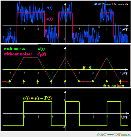
$\text{Example 3:}$ The upper graphic
- shows in red the rectangular transmitted signal $s(t)$ normalized to $\pm 1$,
- which is superimposed by additive noise $n(t)$.
- Shown in blue is the received signal $r(t) = s(t) + n(t)$.
To this graphic it is to be noted further:
- After the receiver filter with a rectangular impulse response of duration $T$, the signal $d(t)$ shown in the middle figure (green curve) is obtained.
- In this special case ("matched filter"), the part $d_{\rm S}(t)$, which is exclusively due to the transmitted signal $s(t)$, has the section–wise linear course shown in red dots.
- The difference $d(t) - d_{\rm S}(t)$ is the noise component $d_{\rm N}(t)$, which originates from the AWGN term $n(t)$.
- The subsequent threshold decision evaluates the detection signal $d(t)$. For this purpose, it compares its samples at the equidistant detection times – marked by yellow arrows in the graphic – with the threshold value $E = 0$.
- Accordingly, the decider sets the sink signal $v(t)$ in the range $\nu \cdot T$ ... $(\nu + 1) \cdot T$ to $+1$ or $-1$, depending on whether the detection sample $d(t)$ is larger or smaller than the decision threshold $E$.
- If the decision unit makes always the correct decision, as in the example shown, its output signal is $v(t) = s(t-T/2)$.
- The delay time of half a symbol duration $(T/2)$ is due to the fact that the detection signal $d(t)$ is sensibly decided in the middle of the symbol, but the provision of the sink signal $v(t)$ can only take place afterwards for reasons of causality.
Block diagram and prerequisites for the first main chapter
The following block diagram is used as a basis for the further sections of this first main chapter. Unless explicitly stated otherwise the following prerequisites apply:

⇒ $q(t)$: source signal ⇒ binary, bipolar and redundancy-free, bit rate $R = 1/T$,
⇒ $s(t)$: transmitted signal ⇒ NRZ–rectangular, amplitude $s_0$, pulse duration $T$,
⇒ $g_s(t)$: basic transmitter pulse ⇒ spectrum $G_s(f)= s_0 \cdot T \cdot {\rm sinc}(f \hspace{0.05cm}T)$,
⇒ $r(t)= s(t) + n(t)$: received signal ⇒ channel frequency response $H_{\rm K}(f) =1$,
⇒ $n(t)$: noise signal ⇒ "AWGN": constant one-sided noise power density $N_0$,
⇒ $d(t) = r(t) \star h_{\rm E} (t)$: detection signal ⇒ after low-pass filtering,
⇒ $h_{\rm E}(t) = {\rm F}^{-1}\big[H_{\rm E}(f)\big]$: impulse response of the receiver filter $H_{\rm E}(f)$,
⇒ $v(t)$: sink signal ⇒ after threshold decision, parameter: $E = 0$, at times $\nu \cdot T$.
- The transmission is binary, bipolar and redundancy-free with bit rate $R = 1/T$. Coded and/or multilevel transmission is dealt with in the "second main chapter".
- The transmitted signal $s(t) = q(t) \star g_s(t)$ is equal to $ \pm s_0$ at all times $t$, i.e.: The basic transmitter pulse $g_s(t)$ is NRZ–rectangular with amplitude $s_0$ and pulse duration $T$.
- Let for the received signal $r(t) = s(t) + n(t)$. Thus, the channel frequency response is always $H_{\rm K}(f) =1$. $n(t)$ is characterized by the constant one-sided (physical) noise power density $N_0$.
- For the detection signal generally applies $d(t) = r(t) \star h_{\rm E} (t)$, where $h_{\rm E}(t) = {\rm F}^{-1}\big[H_{\rm E}(f)\big]$ is the impulse response of the receiver filter with low-pass frequency response $H_{\rm E}(f)$.
- $h_{\rm E}(t)$ is optimally matched to the basic transmitter pulse $g_s(t)$, so that "intersymbol interference" does not play a role. Equalization methods are discussed in the "third main chapter" of this book.
- The parameters of the (binary) threshold decision are optimally chosen: Threshold: $E = 0$, detection times: $\nu \cdot T$.
Exercises for the chapter
Exercise 1.1: Basic Transmitter Pulses
Exercise 1.1Z: Non-redundant Binary Source
References
- ↑ Tröndle, K.; Söder, G.: Optimization of Digital Transmission Systems. Boston – London: Artech House, 1987.


