Technical Innovations of LTE
Contents
For speech transmission with LTE
Unlike previous mobile phone standards, LTE only supports »packet-oriented transmission«. However, for speech transmission (sometimes the term "voice transmission" is used for this), a connection-oriented transmission with fixed reservation of resources would be better, since a "fragmented transmission", as is the case with the packet-oriented method, is relatively complicated.
The problem of integrating speech transmission methods was one of the major challenges in the development of LTE, as speech transmission remains the largest source of revenue for network operators. There were a number of approaches, as it can be seen in the internet article [Gut10][1].
(1) A very simple and obvious method is "Circuit Switched Fallback" $\rm (CSFB)$. Here a wireline transmission is used for the speech transmission. The principle is:
- The terminal device logs on to the LTE network and in parallel also to a GSM or UMTS network. When an incoming call is received, the terminal device receives a message from the "Mobile Management Entity" $\text{(MME}$, control node in the LTE network for user authentication$)$, whereupon a wireline transmission via the GSM or the UMTS network is established.
- A disadvantage of this solution (actually it is a "problem concealment") is the greatly delayed connection establishment. In addition, CSFB prevents the complete conversion of the network to LTE.
(2) Another possibility for the integration of speech/voice in a packet-oriented transmission system is offered by "Voice over LTE via GAN" $\rm (VoLGA)$, which is based on the "Generic Access Network" developed by $\text{3GPP}$. In brief, the principle can be described as follows:
- GAN enables line-based services via a packet-oriented network (IP network), for example $\rm WLAN$ ("Wireless Local Area Network"). With compatible end devices one can register oneself in the GSM network over a WLAN connection and use line-based services. VoLGA uses this functionality by replacing WLAN with LTE.
- The fast implementation of VoLGA is advantageous, as no lengthy new development or changes to the core network are necessary. However, a so-called "VoLGA Access Network Controller" $\rm (VANC)$ must be added to the network as hardware. This takes care of the communication between the end device and the "Mobile Management Entity" or the core network.
Even though VoLGA does not need to use a GSM or UMTS network for voice connections like CSFB, it was considered by the majority of the mobile community as an (unsatisfactory) bridge technology due to its user-friendliness. T–Mobile has long been a proponent of the VoLGA technology, but they also stopped further development in February 2011.
In the following we describe a better solution proposal. Keywords are "IP Multimedia Subsystem" $\rm (IMS)$ and "Voice over LTE" $\rm (VoLTE)$. The operators in Germany switched to this technology relatively late: Vodafone and O2 Telefonica at the beginning of 2015, Telekom at the beginning of 2016.
This is also the reason why the switch to LTE in Germany (and in Europe in general) was slower than in the US. Many customers did not want to pay the higher prices for LTE as long as there was no well functioning solution for integrating voice transmission.
VoLTE - Voice over LTE
From today's point of view (2016), the most promising approach to integrating voice services into the LTE network, some of which are already established, is "Voice over LTE" $\rm (VoLTE)$. This standard, officially adopted by the $\rm GSMA$, the worldwide industry association of more than 800 mobile network operators and over 200 manufacturers of cell phones and network infrastructure, is exclusively IP packet-oriented and is based on the "IP Multimedia Subsystem" $\rm (IMS)$, which was already defined in the UMTS Release 9 in 2010.
The technical facts about IMS are:
- The IMS basic protocol is the one from "Voice over IP" known "Session Initiation Protocol" $\rm (SIP)$. This is a network protocol that can be used to establish and control connections between two users.
- This protocol enables the development of a completely (for data and voice) IP based network and is therefore future-proof.
The reason why the introduction of VoLTE has been delayed by four years compared to LTE establishment in data traffic is due to the difficult interaction of "4G" with the older predecessor standards GSM ("2G") and UMTS ("3G"). Here is an example:
- If a mobile phone user leaves his LTE cell and switches to an area without 4G coverage, an immediate switch to the next best standard (3G) must be made.
- Speech is transmitted here technically completely differently, no longer by many small data packets ⇒ "packet-switched" but sequentially in the logical and physical channels reserved especially for the user ⇒ "circuit-switched".
- This implementation must be so fast and smooth that the end customer does not notice anything. And this implementation must work for all mobile phone standards and technologies.
According to all the experts, VoLTE will have a positive impact on mobile telephony in the same way that LTE has driven the mobile Internet forward since 2011. Key benefits for users are:
- A higher voice quality, as VoLTE uses "AMR wideband codecs" with 12.65 or 23.85 kbit/s. Furthermore, the VoLTE data packets are prioritized for lowest possible latencies.
- An enormously accelerated connection setup within one or two seconds, whereas with "Circuit Switched Fallback" (CSFB) it takes an unpleasantly long time to establish a connection.
- A low battery consumption, significantly lower than "2G" and "3G", associated with a longer battery life. Also in comparison to the usual VoIP services the power consumption is up to 40% lower.
From the provider's point of view, the following advantages result:
- A better spectral efficiency: Twice as many calls are possible in the same frequency band than with "3G". In other words: More capacity is available for data services for the same number of calls.
- An easy implementation of "Rich Media Services" $\rm (RCS)$, e.g. for video telephony or future applications that can be used to attract new customers.
- A better acceptance of the higher provisioning costs by LTE customers if you don't need to outsource to a "low-value" network like "2G" or "3G" for telephony.
Bandwidth flexibility
LTE can be adapted to frequency bands of different widths with relatively little effort by using $\rm OFDM$ ("Orthogonal Frequency Division Multiplex"). This fact is an important feature for various reasons, see [Mey10][2], especially for network operators:
- The frequency bands for LTE may vary in size depending on the legal requirements in different countries. The outcome of the state-specific auctions of LTE frequencies (separated into FDD and TDD) has also influenced the width of the spectrum.
- Often LTE is operated in the "frequency neighborhood" of established radio transmission systems, which are expected to be switched off soon. If the demand increases, LTE can be gradually expanded to the frequency range that is becoming available.
- For example, the migration of television channels after digitalization: A part of the LTE network will be located in the VHF frequency range around 800 MHz, which has now been freed up, see "frequency band splitting graphic".
- Actually the bandwidths could be selected with a degree of fineness of up to 15 kHz (corresponding to an OFDMA subcarrier). However, since this would unnecessarily produce overhead, a duration of »one millisecond« and a bandwidth of »180 kHz« has been specified as the smallest addressable LTE resource. Such a block corresponds to twelve subcarriers (180 kHz divided by 15 kHz).
In order to keep the complexity and effort of hardware standardization as low as possible, a whole range of permissible bandwidths between 1.4 MHz and 20 MHz has been agreed upon. The following list – taken from [Ges08][3] – specifies the standardized bandwidths, the number of available blocks and the "overhead":
- 6 available blocks in the bandwidth 1.4 MHz ⇒ relative overhead about 22.8%,
- 15 available blocks in the bandwidth 3 MHz ⇒ relative overhead about 10%,
- 25 available blocks in the bandwidth 5 MHz ⇒ relative overhead about 10%,
- 50 available blocks in the bandwidth 10 MHz ⇒ relative overhead about 10%,
- 75 available blocks in the bandwidth 15 MHz ⇒ relative overhead about 10%,
- 100 available blocks in the bandwidth 20 MHz ⇒ relative overhead about 10%.
Since otherwise some LTE specific functions would not work, at least six blocks must be provided.
- The relative overhead is comparatively high at small channel bandwidth (1.4 MHz): (1.4 – 6 · 0.18)/1.4 ≈ 22.8%.
- From a bandwidth of 3 MHz the relative overhead is constant 10%.
- It also applies that all end devices must also support the maximum bandwidth of 20 MHz [Ges08][3]
FDD, TDD and half-duplex method
Another important innovation of LTE is the half–duplex procedure, which is a mixture of the two from UMTS already known "duplex procedures":
- »Frequency Division Duplex« $\rm (FDD)$, and
- »Time Division Duplex« $\rm (TDD)$ .
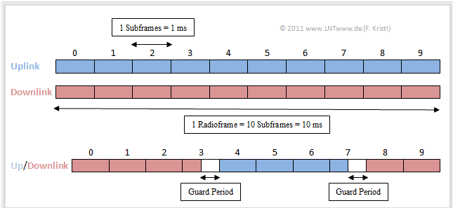
Such duplexing is necessary to ensure that uplink and downlink are clearly separated from each other and that transmission runs smoothly. The diagram illustrates the difference between FDD based and TDD based transmission.
Using the FDD and TDD methods, LTE can be operated in paired and unpaired frequency ranges.
The two methods are present opposing requirements:
- $\rm FDD$ requires a paired spectrum, i.e. one frequency band for transmission from the base station to the terminal ("downlink") and one for transmission in the opposite direction ("uplink"). Downlink and uplink can be used at the same time.
- $\rm TDD$ was designed for unpaired spectra. Now only one band is needed for uplink and downlink. However, transmitter and receiver must now alternate during transmission. The main problem of TDD is the required synchronicity of the networks.
In the graph the differences between FDD and TDD can be seen:
- In TDD a "Guard Period" has to be inserted when changing from downlink to uplink (or vice versa) to avoid an overlapping of the signals.
Although FDD is likely to be used more in practice (and FDD frequencies were much more expensive for the providers), there are several reasons for TDD:
- Frequencies are a rare and expensive commodity, as the 2010 auction has shown. But TDD needs only half of the frequency bandwidth.
- The TDD technique allows different modes, which determine how much time should be used for downlink or uplink and can be adjusted to individual requirements.
For the actual innovation, the $\text{half–duplex}$ method, you need a paired spectrum as with FDD (see the following graphic):
- Base station transmitter and receiver still alternate like TDD. Each terminal device can either transmit or receive at a given time.
- Through a second connection to another end device with swapped downlink/uplink grid, the entire available bandwidth can still be fully used.
- The main advantage of the half–duplex process is that the use of the TDD concept reduces the demands on the end devices and thus allows them to be produced at a lower cost.
The fact that this aspect was of great importance in the standardization can also be seen in the use of "OFDMA" in the downlink and of "SC–FDMA" in the uplink:
- This results in a longer battery life of the end devices and allows the use of cheaper components.
- More about this can be found in chapter "The Application of OFDMA and SC-FDMA in LTE".
Multiple Antenna Systems
If a radio system uses several transmitting and receiving antennas, one speaks of »Multiple Input Multiple Output» $\rm (MIMO)$. This is not an LTE specific development. WLAN, for example, also uses this technology.
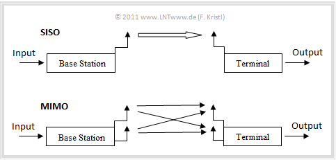
$\text{Example 1:}$ The principle of multiple antenna systems is illustrated in the following graphic using the example of 2×2–MIMO (two transmitting and two receiving antennas).
- The new thing about LTE is not the actual use of "Multiple Input Multiple Output", but the particularly intensive one, namely 2×2 MIMO in the uplink and maximum 4×4 MIMO in the downlink.
- In the successor "LTE Advanced" the use of MIMO is even more pronounced, namely "4×4" in the uplink and "8×8" in the opposite direction.
A MIMO system has advantages compared to "Single Input Single Output" (SISO, only one transmitting and one receiving antenna). A distinction is made between several gains depending on the channel:
- »Power gain« according to the number of receiving antennas:
If the radio signals arriving via several antennas are combined in a suitable way ⇒ "Maximal-ratio combining", the received power is increased and the radio connection is improved. By doubling the antennas, a power gain of maximum 3 dB is achieved.
- »Diversity gain« through "Spatial Diversity":
If several spatially separated receiving antennas are used in an environment with strong multipath propagation, the fading at the individual antennas is mostly independent from each other and the probability that all antennas are affected by fading at the same time is very low.
- »Data rate gain«:
This increases the efficiency of MIMO, especially in an environment with increased multipath propagation, especially when transmitter and receiver do not have a direct line of sight and the transmission is done via reflections. Tripling the number of antennas for the transmitter and receiver results in approximately twice the data rate.
However, it is not possible for all advantages to occur simultaneously. Depending on the nature of the channel, it can also happen that one does not even have the choice of which advantage one wants to use.
In addition to the MIMO systems there are also the following intermediate stages:
- MISO systems (only one receiving antenna, therefore no power gain is possible), and
- SIMO systems (only one transmitting antenna, therefore only small diversity gain).
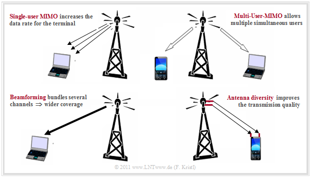
$\text{Example 2:}$ The term "MIMO" summarizes multi-antenna techniques with different properties, each of which can be useful in certain situations. The following description is based on the four diagrams shown here.
- If the mostly independent channels of a MIMO system are assigned to a single user (top left diagram), one speaks of "Single–User MIMO". With 2×2 MIMO, the data rate is doubled compared to SISO operation and with four transmitting and receiving antennas each, the data rate can be doubled again under good channel conditions.
- LTE allows maximum 4×4 MIMO but only in the downlink. Due to the complexity of multi-antenna systems, only laptops with LTE modems can be used as receivers (end devices) for 4×4 MIMO. For a mobile phone, the use is generally limited to 2×2 MIMO.
- Contrary to Single–User MIMO, the goal with the »Multi–User MIMO« is not the maximum data rate for a receiver, but the maximization of the number of end devices that can use the network simultaneously (top right diagram).
- This involves transmitting different data streams to different users. This is particularly useful in places with high demand, such as airports or soccer stadiums.
- This involves transmitting different data streams to different users. This is particularly useful in places with high demand, such as airports or soccer stadiums.
- Multi-antenna operation is not only used to maximize the number of users or data rate, but also in the event of poor transmission conditions, multiple antennas can combine their power to transmit data to a single user to improve the quality of reception. One then speaks of »Beamforming« (diagram below left), which also increases the range of a transmitting station.
- The fourth possibility is »Antenna diversity« (diagram below right). This increases the redundancy (regarding the system design) and makes the transmission more robust against interferences.
- A simple example: There are four channels that all transmit the same data. If one channel fails, there are still three channels for information transport.
System Architecture
The LTE architecture enables a transmission system based entirely on the IP protocol. In order to achieve this goal, the system architecture specified for UMTS not only had to be changed in detail, but in some cases completely redesigned. In the process, other IP based technologies such as "mobile WiMAX" or "WLAN" were also integrated in order to be able to switch to these networks without any problems.
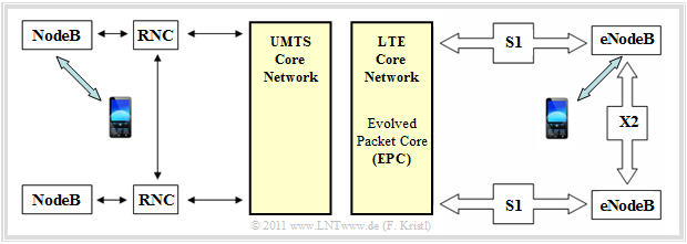
In UMTS networks (left graphic), the "Radio Network Controller" $\rm (RNC)$ is inserted between a base station ("NodeB") and the core network, which is mainly responsible for switching between different cells and which can lead to latency times of up to 100 milliseconds.
- The redesign of the base stations ("eNodeB" instead of "NodeB") and the interface "X2" are the decisive further developments from UMTS towards LTE.
- The graphic on the right illustrates in particular the reduction in complexity compared to UMTS that goes hand in hand with the new technology (left graphic).
The $\text{LTE system architecture}$ can be divided into two major areas, too:
- the LTE core network "Evolved Packet Core" $\rm (EPC)$,
- the air interface "Evolved UMTS Terrestrial Radio Access Network" $\rm (EUTRAN)$, a further development of "UMTS Terrestrial Radio Access Network" $\rm (UTRAN)$.
EUTRAN transmits the data between the terminal and the LTE base station ("eNodeB") via the so-called "S1" interface with two connections, one for the transmission of user data and a second for the transmission of signalling data. You can see from the above graphic:
- The base stations are connected not only to the EPC but also to the neighboring base stations. These connections ("X2" interfaces) have the effect that as few packets as possible are lost when the terminal device moves from the vicinity of one base station towards another.
- For this purpose, the base station whose service area the user is just leaving can pass on any cached data directly and quickly to the "new" base station. This ensures (largely) continuous transmission.
- The functionality of the "RNC" is partly transferred to the base station and partly to the "Mobility Management Entity" $\rm (MME)$ in the core network. This reduction of the interfaces significantly shortens the signal throughput time in the network and the handover to 20 milliseconds.
- The LTE system architecture is also designed so that future "Inter–NodeB procedures" (such as "Soft Handover" or "Cooperative Interference Cancellation") can be easily integrated.
LTE core network: Backbone and Backhaul
The LTE core network "Evolved Packet Core" $\rm (EPC)$ of a network operator (in the technical language "Backbone") consists of various network components. The EPC is connected to the base stations via the "Backhaul". This means the connection of an upstream, usually hierarchically subordinated network node to a central network node.
Currently, the "Backhaul" consists mainly of directional radio and so-called "E1" lines. These are copper lines and allow a throughput of about 2 Mbit/s. For GSM and UMTS networks these connections were still sufficient, however, for the large-scale conceived $\rm HSDPA$ such data rates are no longer adequate. For LTE such a "Backhaul" is completely unusable:
- The slow cable network would slow down the fast wireless connections; overall, there would be no increase in speed.
- Due to the low capacities of the lines with "E1" standard, an expansion with further lines of the same construction would not be economical.
In the course of the introduction of LTE, the backhaul had to be redesigned. It was important to keep an eye on future security, since the next generation "LTE Advanced" was already in place before the introduction. If one believes the experts' propaganda "Moore's Law" for mobile phone bandwidths, the most important factor for future security is the expensive new installation of better cables.
Due to the purely packet-oriented transmission technology, the Ethernet standard, which is also IP based, is suitable for the LTE backhaul, which is realized with the help of optical fibers. In 2009, the company Fujitsu presented in the study [Fuj09][4], also the thesis that the current infrastructure will continue to play an important role for LTE backhaul for the next ten to fifteen years.
There are two approaches for the generation change to an Ethernet based backhaul :
- the parallel operation of the lines with "E1" and Ethernet standard,
- the immediate migration to an Ethernet based backhaul.
The former would have the advantage that the network operators could continue to run voice traffic over the old lines and would only have to handle bandwidth-intensive data traffic over the more powerful lines.
The second option raises some technical problems:
- The services previously transported through the slow "E1" standard lines would have to be switched immediately to a packet-based procedure.
- Ethernet does not offer (unlike the current standard) any end–to–end synchronization, which can lead to severe delays or even service interruptions when changing radio cells, thus a huge loss of service quality.
- However, in the concept "Synchronous Ethernet" $\rm (SyncE)$, the Cisco company has already made suggestions as to how synchronization could be realized.
For conurbations, a direct conversion of the backhaul would certainly be worthwhile, as relatively few new cables would have to be laid for a comparatively high number of new users.
In rural areas, however, major excavation work would quickly result in high costs. However, this is exactly the area which must be covered first, according to the "agreement reached" between the federal government and the (German) mobile phone operators. Here, the mostly existing microwave radio link would have to be (and probably will be) extended to high data rates.
Exercises for the chapter
Exercise 4.2: FDD, TDD and Half-Duplex
Exercise 4.2Z: MIMO Applications in LTE
References
- ↑ Gutt, E.: LTE - a new dimension of mobile broadband use. "PDF Internet document", 2010.
- ↑ Meyer, M.: Siebenmeilenfunk. c't 2010, issue 25, 2010.
- ↑ 3.0 3.1 Gessner, C.: UMTS Long Term Evolution (LTE): Technology Introduction. Rohde&Schwarz, 2008.
- ↑ Fujitsu Network Communications Inc.: 4G Impacts to Mobile Backhaul. "PDF Internet document".


