Difference between revisions of "Modulation Methods/Linear Digital Modulation"
| (53 intermediate revisions by 7 users not shown) | |||
| Line 1: | Line 1: | ||
{{Header | {{Header | ||
| − | |Untermenü= | + | |Untermenü=Digital Modulation Methods |
| − | |Vorherige Seite= | + | |Vorherige Seite=Pulse Code Modulation |
| − | |Nächste Seite= | + | |Nächste Seite=Quadrature Amplitude Modulation |
}} | }} | ||
| − | == | + | ==Differences between analog and digital modulation methods== |
| − | + | <br> | |
| + | The diagram shows an analog transmission system at the top and a digital system drawn below. The main differences are highlighted in red: | ||
| + | [[File:EN_Mod_T_4_2_S1.png |right|frame|Analog and digital transmission system]] | ||
| + | While in the upper system the analog source signal $q(t)$ is applied to the modulator input, in the lower digital system the modulating signal $q_{\rm D}(t)$ is a digital signal, characterized by the amplitude coefficients $a_ν$, the basic pulse $g_q(t)$ and the symbol duration $T$: | ||
| + | :$$q_{\rm D}(t) = \sum_{\nu=-\infty}^{+\infty}a_\nu \cdot g_q(t - \nu \cdot T) \hspace{0.05cm}.$$ | ||
| − | [[ | + | *The A/D conversion can be done for example by [[Modulation_Methods/Pulse_Code_Modulation|$\text{pulse code modulation}$]] and includes the functions sampling, quantization, binary coding and signal shaping. |
| + | *The basic pulse $g_q(t)$ is often assumed to be NRZ-rectangular with amplitude $s_0$ and duration $T$. For the spectral function holds with ${\rm sinc}(x) = \sin(\pi x)/(\pi x)$: | ||
| + | :$$G_q(f) = s_0 · T · {\rm sinc}(f T).$$ | ||
| + | *The modulators can be the same for both systems. They change one of the three signal parameters of the carrier $z(t)$ according to the modulator input. The digital variants of AM, PM, FM are called | ||
| + | #"Amplitude Shift Keying" $\rm (ASK)$, | ||
| + | #"Phase Shift Keying" $\rm (PSK)$, | ||
| + | #"Frequency Shift Keying" $\rm (FSK)$. | ||
| − | + | *In contrast, the demodulator of the digital system differs fundamentally from an analog demodulator by the required decision component (in hardware or software). Like $q_{\rm D}(t)$, the demodulator output signal $v_{\rm D}(t)$ is digital and must then be D/A converted into the analog sink signal $v(t)$. | |
| − | * | + | |
| − | + | *The decisive quality criterion for both systems is the [[Modulation_Methods/Quality_Criteria#Signal.E2.80.93to.E2.80.93noise_.28power.29_ratio|$\text{sink SNR}$]] ⇒ quotient of the power of source signal $q(t)$ and error signal $ε(t) = v(t) \ – \ q(t)$. In a digital system, one usually makes do with the quality characteristic [[Digital_Signal_Transmission/Error_Probability_for_Baseband_Transmission#Definition_of_the_bit_error_rate|$\text{bit error rate}$]] $($ $\rm BER)$, which refers to the digital signals $q_{\rm D}(t)$ and $v_{\rm D}(t)$. This can be converted into a $\rm SNR$. | |
| − | * | ||
| − | |||
| − | |||
| − | |||
==ASK – Amplitude Shift Keying== | ==ASK – Amplitude Shift Keying== | ||
| − | + | <br> | |
| + | The diagram shows the digital source signal $q(t)$ – the index "D" is omitted from now on – and the ASK transmitted signal | ||
| + | [[File:P_ID1688__Mod_T_4_2_S2_neu.png|right|frame|Signals and power-spectral density $\rm (PSD)$ at ASK]] | ||
| + | |||
| + | :$$s_{\rm ASK}(t) = q(t) · \sin(2π · f_{\rm T} · t),$$ | ||
| + | where unipolar amplitude coefficients $a_ν ∈ \{0, \ 1\}$ and a sinusoidal carrier (German: "Träger" ⇒ subscript "T") with frequency $f_{\rm T}$ are assumed here. | ||
| + | |||
| + | For example, this method is used in optical transmission systems (since there are no negative light pulses) and is also known as "On–Off–Keying". | ||
| + | |||
| + | In the right half of the figure, the corresponding power-spectral densities are shown - although not to scale. | ||
| + | |||
| + | With the rectangular basic pulse $g_q(t)$ and equally probable unipolar amplitude coefficients holds: | ||
| + | :$$\begin{align*}{{\it \Phi}_{q}(f)}& = \frac{{s_0}^2 \cdot T}{4} \cdot {\rm sinc}^2 (f T) + \frac{{s_0}^2 }{4} \cdot \delta (f)\hspace{0.05cm},\\ {{\it \Phi}_{s}(f)}& = \frac{1}{4} \cdot \big [ {{\it \Phi}_{q}(f- f_{\rm T})}+ {{\it \Phi}_{q}(f+ f_{\rm T})}\big]\hspace{0.05cm}.\end{align*}$$ | ||
| + | |||
| + | It should be noted about these equations: | ||
| + | #The DC component $m_q = s_0/2$ of the source signal leads to a Dirac delta function at frequency $f = 0$ with weight ${s_0}^2/4$ in the power-spectral density $ϕ_q(f)$. | ||
| + | #The power-spectral density of the ASK transmitted signal $s(t)$ is equal to $ϕ_s(f) = ϕ_q(f) ∗ ϕ_z(f)$, where the PSD $ϕ_z(f)$ of the carrier $z(t)$ is composed of two Dirac delta functions at $±f_{\rm T}$ with respective weight $1/4$. The sign "$\star$" describes the convolution. The equation is also valid with other carrier phase. | ||
| + | #The power-spectral density $ϕ_s(f)$ is identical in shape to $ϕ_q(f)$ except for the shift by $±f_{\rm T}$ ⇒ the ASK belongs to the »'''linear digital modulation methods'''«. | ||
| + | ==Coherent demodulation of ASK signals== | ||
| + | <br> | ||
| + | The diagram shows the block diagram of an ASK system including the receiver components. | ||
| + | [[File:EN_Mod_T_4_2_S3a_neu.png|right|frame|Block diagram of an ASK system including receiver components]] | ||
| + | *Let the source signal $q(t)$ be NRZ-rectangular and unipolar: | ||
| + | :$$a_ν ∈ \{0, \ 1\}.$$ | ||
| + | * Let the channel be initially ideal, characterized by | ||
| + | :$$H_{\rm K}(f) = 1,\hspace{0.25cm} n(t) = 0 \hspace{0.5cm} \Rightarrow \hspace{0.5cm} r(t) = s(t).$$ | ||
| − | [[ | + | The demodulation is performed coherently by means of a [[Modulation_Methods/Synchrondemodulation|$\text{synchronous demodulator}$]], the operation of which has already been described for the analog modulation methods AM and PM. |
| + | To summarize the block diagram: | ||
| + | *At the receiver the same carrier signal is added as at the transmitter, but with double amplitude. | ||
| + | *$z(t)$ denotes the carrier at the transmitter ⇒ the carrier at the receiver (German: "Empfänger" ⇒ subscript "E") is $z_{\rm E}(t) = 2 · z(t) $. | ||
| + | *Multiplication is followed by a suitably sized low-pass filter with frequency response $H_{\rm E}(f)$, which removes the higher frequency components of the signal $b(t)$. | ||
| + | *The detection signal $d(t)$ is sampled at instants $ν · T$ and decided using a threshold decision with threshold $E = {s_0}/2$. | ||
| + | *The sink signal $v(t)$ at the decision output is rectangular and in the noise-free case equal to the source signal $q(t)$ except for the transit time $T/2$. | ||
| − | |||
| − | |||
| − | + | {{BlaueBox|TEXT= | |
| − | * | + | $\text{To be noted:}$ |
| − | * | + | *»'''Coherent demodulation'''« requires that the carrier frequency $f_{\rm T}$ and the carrier phase $ϕ_{\rm T}$ are exactly known to the receiver. |
| − | + | *The receiver '''must extract these two quantities from the received signal $r(t)$''', which can be quite costly in the presence of strong channel distortion and large noise $n(t)$. Such realization aspects are dealt with, for example, in [[Aufgaben:Exercise_4.9:_Costas_Rule_Loop|"Exercise 4.9"]] to this chapter. | |
| + | *If the carrier phase $ϕ_{\rm T}$ is not known to the receiver, this is called »'''incoherent demodulation'''«, even if the carrier frequency $f_{\rm T}$ is known.}} | ||
| − | |||
| − | |||
| + | {{GraueBox|TEXT= | ||
| + | $\text{Example 1:}$ The diagram shows the signals mentioned in the ASK block diagram with ideal channel: $H_{\rm K}(f) = 1, \ \ n(t) = 0.$ | ||
| + | [[File:EN_Mod_T_4_2_S3b.png |right|frame| Signals with ASK modulation and coherent demodulation]] | ||
| + | |||
| + | The individual signal characteristics can be interpreted as follows: | ||
| + | *The transmitted signal $s(t)$ is the product of the unipolar source signal $q(t)$ and the carrier signal $z(t) = \sin(2π\hspace{0.05cm}f_{\rm T}\hspace{0.05cm}t)$, where in the example $f_{\rm T} = 4/T$ holds (only four oscillations per symbol duration). | ||
| + | *The received signal $r(t) = s(t)$ is first multiplied by the receiver-side carrier $z_{\rm E}(t) = 2 · \sin(2π\hspace{0.05cm}f_{\rm T}\hspace{0.05cm}t)$ ⇒ twice the amplitude compared to $z(t)$, no frequency and phase offset. This gives: | ||
| + | :$$b(t) = 2 \cdot z(t)\cdot r(t)= 2 \cdot z^2(t)\cdot q(t) $$ | ||
| + | :$$\Rightarrow \hspace{0.35cm}b(t) = q(t) \cdot \big [ 1 - \cos(4\pi\hspace{0.05cm} f_{\rm T}\hspace{0.05cm} t)\big] | ||
| + | \hspace{0.05cm}.$$ | ||
| + | *The low-pass filter with frequency response $H_{\rm E}(f) = {\rm sinc}(f_{\rm T}\hspace{0.05cm} T)$ and corresponding rectangular impulse response $h_{\rm E}(t)$ forms from the signal $b(t)$ the detection signal $d(t) = b(t) \star h_{\rm E}(t)$ . | ||
| + | * $h_{\rm E}(t)$ is matched to the rectangular basic pulse $g_q(t)$. This is called the [[Theory_of_Stochastic_Signals/Matched_Filter|$\text{matched filter configuration}$]] ⇒ best possible compromise between equalization and noise power limitation. | ||
| + | *In the absence of noise ⇒ $d(νT) = q(νT) ∈ \{0, \ s_0\}$. In the presence of (moderate) noise, it is very likely that $d(νT) > s_0/2,$ if $a_ν = +1$, and it will be $d(νT) < s_0/2$ for $a_ν = 0$. | ||
| + | *The decision obtains from the comparison of the samples $d(νT)$ with the threshold $E = s_0/2$ the sink signal $v(t)$, which is equal to $q(t)$ if the decision is error-free except for the transit time $T/2$. }} | ||
| − | [[File: | + | ==Incoherent demodulation of ASK signals== |
| + | <br> | ||
| + | We further assume ASK modulation as well as an ideal transmission channel, i.e. | ||
| + | [[File:EN_Mod_T_4_2_S4a_neu.png|right|frame|Block diagram of an incoherent ASK demodulator]] | ||
| + | #distortion-free, | ||
| + | #attenuation-free and | ||
| + | #noise-free. | ||
| − | + | Then applies: $r(t) = s(t) = q(t) \cdot \cos(2 \pi \cdot f_{\rm T} \cdot t + \phi_{\rm T})\hspace{0.05cm}.$ | |
| − | + | Further, it is assumed for this section | |
| − | + | *that the receiver knows the carrier frequency $f_{\rm T}$, | |
| − | * | + | *but not the carrier phase $ϕ_{\rm T}$. |
| − | * | ||
| − | |||
| + | The diagram shows such an »'''incoherent demodulator'''« ⇒ the '''result of the demodulator is independent of the carrier phase $ϕ_{\rm T}$''', which the receiver does not know. | ||
| − | {{ | + | The operation of this demodulator will be given here only as an outline: |
| − | + | *The signals $d_1(t)$ and $d_2(t)$ after the two [[Theory_of_Stochastic_Signals/Matched_Filter|$\text{matched filters}$]] with respective frequency response $H_{\rm E}(f)$ are identical in shape to the detection signal $d(t)$ ⇒ $d_{\rm coh}(t)$ according to the [[Modulation_Methods/Linear_Digital_Modulation#Coherent_demodulation_of_ASK_signals|$\text{previous block diagram}$]], but generally attenuated with respect to it due to the lack of phase matching: | |
| − | {{end}} | + | :$$d_1(t) = d_{\rm coh}(t) \cdot \cos( \phi_{\rm T}), \hspace{0.5cm}d_2(t) = -d_{\rm coh}(t) \cdot \sin( \phi_{\rm T}) \hspace{0.05cm}.$$ |
| + | *If the amplitude coefficient is $a_ν = 0$, then in the noise-free case the two signal values are zero: | ||
| + | :$$d_1(ν · T) = 0,\hspace{0.5cm} d_2(ν · T) = 0.$$ | ||
| + | *Otherwise $(a_ν = 1)$ applies: | ||
| + | :$$d_1(\nu \cdot T) = s_{\rm 0} \cdot \cos( \phi_{\rm T}), | ||
| + | \hspace{0.5cm}d_2(\nu \cdot T) = -s_{\rm 0} \cdot \sin( \phi_{\rm | ||
| + | T}) \hspace{0.05cm}.$$ | ||
| + | *After squaring the two partial signals we get for the sum signal: | ||
| + | :$$d(\nu \cdot T) = \left\{ \begin{array}{c} 0 \\ {s^2_0} \end{array} \right.\quad | ||
| + | \begin{array}{*{1}c} {\rm if}\hspace{0.15cm}a_\nu = 0, | ||
| + | \\ {\rm if}\hspace{0.15cm}a_\nu = 1. \\ \end{array}$$ | ||
| + | *By threshold decision – sensibly with the decision threshold $E = {s_0}^2/2$ – the amplitude coefficients $a_ν$ can be decided. <br>However in the noisy case, this results in a somewhat larger [[Modulation_Methods/Linear_Digital_Modulation#Error_probabilities_-_a_brief_overview|$\text{bit error probability}$]] than with coherent demodulation. | ||
| − | == | + | ==BPSK – Binary Phase Shift Keying== |
| − | + | <br> | |
| + | For [[Modulation_Methods/Phasenmodulation_(PM)|$\text{analog phase modulation}$]] $\rm (PM)$, the transmitted signal is: $s_{\rm PM}(t) = s_0 \cdot \cos\big [2 \pi f_{\rm T} t + \phi_{\rm T}+ | ||
| + | K_{\rm PM} \cdot q(t)\big ]\hspace{0.05cm}.$ With | ||
| + | [[File:P_ID1692__Mod_T_4_2_S5_ganz_neu.png |right|frame| Signals and power-spectral densities $\rm (PSD)$ for Binary Phase Shift Keying]] | ||
| + | #bipolar source signal ⇒ $a_ν ∈ \{-1, +1\}$, | ||
| + | #carrier phase $ϕ_{\rm T} = π \ (180^\circ)$ | ||
| + | #modulator constant $K_{\rm PM} = π/(2s_0)$, | ||
| − | + | we obtain in the $ν$–th time interval: | |
| + | :$$s_{\rm BPSK}(t) = \left\{ \begin{array}{c} s_0 \cdot \cos(2 \pi f_{\rm T} t + | ||
| + | \pi+ \pi/2) \\ s_0 \cdot \cos(2 \pi f_{\rm T} t + \pi- \pi/2) \end{array} \right.\quad \begin{array}{*{1}c} {\rm if}\hspace{0.15cm}a_\nu = +1, \\ {\rm if}\hspace{0.15cm}a_\nu = -1. \\ \end{array}$$ | ||
| + | This equation for »'''Binary Phase Shift Keying'''« $($ $\rm BPSK)$ can be transformed as follows: | ||
| + | :$$s_{\rm BPSK}(t) = | ||
| + | a_\nu \cdot s_0 \cdot \sin(2 \pi f_{\rm T} t ) $$ | ||
| + | :$$\Rightarrow \hspace{0.3cm}s_{\rm BPSK}(t) = \left\{ \begin{array}{c} s_0 \cdot \sin(2 \pi f_{\rm T} t ) \\ | ||
| + | -s_0 \cdot \sin(2 \pi f_{\rm T} t ) \end{array} \right.\quad \begin{array}{*{1}c} {\rm if}\hspace{0.15cm}a_\nu = +1, \\ {\rm if}\hspace{0.15cm}a_\nu = -1. \\ \end{array}$$ | ||
| + | <br clear=all> | ||
| + | In the diagram the signals and the corresponding power-spectral densities are sketched. It can be seen: | ||
| + | *Like the ASK signal, the BPSK signal can be represented as the product of the source signal $q(t)$ and the carrier signal $z(t)$. The only difference lies in the bipolar amplitude coefficients $a_ν ∈ \{-1, +1\}$ compared to the unipolar coefficients $(0$ or $1)$ with ASK. | ||
| + | *In contrast to ASK, with BPSK $($as with any form of phase modulation$)$ the envelope is constant. The information is transmitted here by the phase jumps within the transmitted signal $s(t)$ ⇒ gray backgrounds in the diagram. | ||
| + | *The power-spectral densities with BPSK differ from those with ASK only by the missing Dirac delta functions $($since now $q(t)$ does not contain a DC component$)$ and by the factor $4$ with respect to the continuous PSD components. | ||
| + | *It further follows that binary phase modulation $\rm (BPSK)$ can be counted as a linear modulation method. In general, (analog) phase modulation $\rm (PM)$ is, with a few exceptions, non-linear with respect to the source signal. | ||
| + | *For the diagrams, different carrier phases were chosen for display reasons in the section [[Modulation_Methods/Lineare_digitale_Modulation#ASK_.E2.80.93_Amplitude_Shift_Keying|"ASK"]] ⇒ "sine" and here for "BPSK" ⇒ "minus cosine". However, this arbitrary determination is not a restriction. Both methods work in the same way for other carrier phases. | ||
| + | |||
| + | ==Demodulation and detection of BPSK signals== | ||
| + | <br> | ||
| + | Due to the constant envelope of the BPSK signal, the demodulation must always be coherent here. The [[Modulation_Methods/Linear_Digital_Modulation#Coherent_demodulation_of_ASK_signals|$\text{same block diagram}$]] can be assumed as for coherent ASK demodulation. | ||
| + | |||
| + | [[File:EN_Mod_T_4_2_S4b.png|right|frame|Signals with BPSK modulation and coherent demodulation]] | ||
| + | {{GraueBox|TEXT= | ||
| + | $\text{Example 2:}$ The diagram shows from top to bottom | ||
| + | #the bipolar source signal $q(t)$, | ||
| + | #the received signal $r(t) = s(t)$ with ideal channel, | ||
| + | #$b(t)$ after multiplication by the receiver-side carrier $z_{\rm E}(t) = 2 \cdot z(t)$, | ||
| + | #the detection signal $d(t)$ after "integration" by the matched filter, | ||
| + | #the sink signal $v(t)$. | ||
| − | |||
| − | |||
| − | |||
| − | |||
| − | |||
| − | |||
| − | |||
| − | |||
| − | |||
| − | + | A comparison with the corresponding [[Modulation_Methods/Linear_Digital_Modulation#Coherent_demodulation_of_ASK_signals|$\text{signals}$]] in the coherent demodulation of the ASK shows: | |
| − | + | *The rectangular signals $q(t)$ and $v(t)$ are now bipolar. | |
| − | $ | ||
| − | |||
| − | + | *For the detection signal at BPSK, compared to ASK, the following applies: | |
| + | :$$d_{\rm BPSK}(t) =2 \cdot d_{\rm ASK}(t)-s_0.$$ | ||
| + | *In the considered attenuation-free, distortion-free and noise-free case, all detection samples are $d(ν · T) = ±s_0$. Therefore, the decision threshold $E = 0$ should be used here. | ||
| − | + | ||
| − | * | + | *One can see the double distance of the BPSK detection samples (circle marks) from the threshold, which decisively improves [[Modulation_Methods/Linear_Digital_Modulation#Error_probabilities_-_a_brief_overview|$\text{error probability}$]]. }} |
| − | |||
| − | |||
| − | |||
| − | \ | ||
| − | |||
| − | |||
| − | |||
| − | |||
| − | |||
| − | |||
| − | |||
| − | |||
| − | |||
| − | |||
| − | |||
| − | |||
| − | |||
| − | |||
| − | |||
| − | |||
| − | |||
| + | ==DPSK – Differential Phase Shift Keying== | ||
| + | <br> | ||
| + | [[File:EN_Mod_T_4_2_S7.png|right|frame| DPSK transmitter]] | ||
| + | The diagram on the right shows the block diagram of the modulator for "Differential Phase Shift Keying" $\rm (DPSK)$. | ||
| + | *The bipolar source signal $q(t)$ with the amplitude coefficients $q_ν ∈ \{-1, +1\}$ is transformed according to this mapping into the signal $m(t)$ with the amplitude coefficients | ||
| + | :$$m_{\nu} = m_{\nu -1} \cdot q_{\nu} \in \{ -1, +1\}$$ | ||
| + | :before it is fed to the BPSK modulator. | ||
| − | |||
| + | *If $q_ν = m_{ν-1}$, the mapped amplitude coefficient is $m_ν = +1$. In contrast, $m_ν = -1$ indicates that the amplitude coefficients $q_ν$ and $m_{ν-1}$ are different. | ||
| − | |||
| − | |||
| − | |||
| − | |||
| − | |||
| − | |||
| − | + | *An essential advantage of differential binary phase modulation is that the resulting signal $s(t)$ can be demodulated even without knowledge of the carrier phase $ϕ_{\rm T}$, see next section. Although the exact carrier frequency $f_{\rm T}$ must be known to the receiver, it is still referred to as an "incoherent PSK demodulator", and sometimes as a "differential coherent PSK demodulator". | |
| − | + | <br clear=all> | |
| + | [[File:EN_Mod_T_4_2_S7b.png|right|frame|Signals at the DPSK transmitter]] | ||
| + | {{GraueBox|TEXT= | ||
| + | $\text{Example 3:}$ | ||
| + | The diagram on the right shows | ||
| + | #the bipolar source signal $q(t)$, | ||
| + | #the mapping signal $m(t)$, and | ||
| + | #the DPSK transmitted signal $s(t)$. | ||
| − | + | In the following, $v_ν$ denotes the coefficients after the decision, which should coincide with the transmission-side amplitude coefficients $q_ν$. | |
| + | The following principle can be seen: | ||
| + | *Whenever the receiver detects a phase jump, it decides $v_ν = -1$: | ||
| + | :$$v_3 = v_5 =v_6 =-1.$$ | ||
| + | *If no phase jump is recognizable, $v_ν = +1$ is set: | ||
| + | :$$v_1 = v_2 =v_4 =+1.$$ | ||
| − | + | Below the phase values $ϕ_{\rm S}$ are given for the first six symbols: | |
| − | * | + | *Additional phase rotation on the channel, e.g. by $70.3π$, does change the absolute phase values to $69.8π$, $69.8π$, $70.8π$, $70.8π$, $69.8π$ and $70.8π$. |
| − | $$ | + | *However, the phase difference of adjacent symbols is preserved, so the differential coherent demodulation still works. |
| − | + | *A corresponding demodulator is presented in the following section. }} | |
| − | |||
| − | * | ||
| − | ==DPSK | + | ==Differential coherent demodulation of the DPSK signal== |
| − | [[File: | + | <br> |
| − | + | The graphic shows the block diagram of a transmission system with DPSK modulation ("Differential Phase Shift Keying") and differential coherent demodulation. In bullet point form, the given system can be described as follows: | |
| − | $$m_{ | + | [[File:EN_Mod_T_4_2_S7c_neu.png|right|frame| DPSK modulation and differential coherent demodulation]] |
| + | *Ignoring the modulation with the carrier signals $z(t)$ and $2 · z(t)$ resp., the symbol $m_ν = m_{ν-1} · q_ν$ is present in the interval $ν$ at input '''(1)''' of the multiplier highlighted in yellow, and the symbol $m_{ν-1}$ is present at input '''(2)'''. | ||
| + | *The multiplication of '''(1)''' and '''(2)''' gives the desired result: | ||
| + | :$$v_ν = m_{ν-1} · q_ν · m_{ν-1} = q_ν.$$ | ||
| + | :It is taken into account here that $m_{ν-1} ∈ \{+1, –1\}$ holds. | ||
| + | *The matched filter with frequency response $H_{\rm E}(f)$ eliminates the unwanted components around the doubled carrier frequency $(\pm f_{\rm T})$ which result from the twofold multiplication by transmitter-side carrier $z(t)$ and receiver-side carrier $2 · z(t)$. With rectangular pulse $g_q(t)$ ⇒ $H_{\rm E}(f)$ can be realized by an integrator. | ||
| − | |||
| − | + | We now assume that the channel causes a phase rotation by $ϕ$, which the receiver does not know (red block): | |
| + | #For example, assuming the transmitter-side carrier $z(t) = \cos (2π · f_{\rm T} · t)$, the received signal $r(t)$ contains a multiplicative component with $\cos (2π · f_{\rm T} · t + ϕ)$. Thus, the addition of the receiver-side carrier $2 · z(t)$ is not phase synchronous. | ||
| + | #The signal $r(t – T)$ delayed by a symbol duration $T$ has the same phase $ϕ$. The correlation between $2 · r(t) · z(t)$ and $2 · r(t – T) · z(t – T )$ makes the decision result independent of the random phase $ϕ$. This type of demodulation is called "differential-coherent". | ||
| − | |||
| + | ==Error probabilities - a brief overview== | ||
| + | <br> | ||
| + | The error probabilities of the discussed digital modulation methods (ASK, BPSK, DPSK) are calculated in chapter [[Digital_Signal_Transmission/Lineare_digitale_Modulation_–_Kohärente_Demodulation|"Linear Digital Modulation - Coherent Demodulation"]] of the book "Digital Signal Transmission" under different boundary conditions. Here only some results are given without proof, valid for | ||
| + | #a transmitted signal with the average energy $E_{\rm B}$ per bit, | ||
| + | #AWGN noise with the (one-sided) noise power density $N_0$, and | ||
| + | #best possible receiver realization using the matched filter principle. | ||
| − | |||
| − | |||
| + | {{BlaueBox|TEXT= | ||
| + | $\text{Here without proof:}$ | ||
| + | Let us first consider the »'''bit error probability'''« of [[Modulation_Methods/Linear_Digital_Modulation#Demodulation_and_detection_of_BPSK_signals|$\text{Binary Phase Shift Keying}$]] $\rm (BPSK)$ assuming a coherent receiver: | ||
| + | ::$$p_{\text{B, BPSK, coh} } = {\rm Q}\left ( \sqrt{ {2 \cdot E_{\rm B} }/{N_0 } } \hspace{0.1cm}\right | ||
| + | ) = {1}/{2}\cdot {\rm erfc}\left ( \sqrt{ {E_{\rm B} }/{N_0 } } \hspace{0.1cm}\right ).$$ | ||
| + | *[[Applets:Komplementäre_Gaußsche_Fehlerfunktionen|"Two variants of the complementary Gaussian error function"]] were used in the formulas: | ||
| + | ::$${\rm Q} ({\it x}) = \frac{\rm 1}{\sqrt{\rm 2\pi} }\int_{\it | ||
| + | x}^{+\infty}{\rm e}^{ {\it -u}^{\rm 2}/\rm 2}\,{\rm d} {\it u} | ||
| + | \hspace{0.05cm},\hspace{0.3cm} {\rm erfc} ( {\it x} ) = \frac{\rm | ||
| + | 2}{\sqrt{\rm \pi} }\int_{\it x}^{+\infty}{\rm e}^{ {\it -u}^{\rm | ||
| + | 2} }\,{\rm d} {\it u} \hspace{0.05cm}.$$ | ||
| + | *In contrast, for [[Modulation_Methods/Linear_Digital_Modulation#Coherent_demodulation_of_ASK_signals|$\text{Amplitude Shift Keying}$]] $\rm (ASK)$ with coherent demodulation: | ||
| + | ::$$p_{\text{B, ASK, coh} } = {\rm Q}\left ( \sqrt{{E_{\rm B} }/{N_0 } } \hspace{0.1cm}\right | ||
| + | ) ={1}/{2}\cdot {\rm erfc}\left ( \sqrt{ {E_{\rm B}}/{(2 \cdot N_0) } } \hspace{0.1cm}\right ).$$ | ||
| + | ::If we plot the bit error probability over the quotient $E_{\rm B}/N_0$ in double logarithmic scale, the ASK curve is always $3 \ \rm dB$ to the right of the BPSK curve. This degradation is one of the reasons why ASK is rarely used in practice. | ||
| + | *The decisive advantage of [[Modulation_Methods/Linear_Digital_Modulation#Differential_coherent_demodulation_of_the_DPSK_signal|$\text{Differential Phase Shift Keying}$]] $\rm (DPSK)$ is that it '''can be demodulated without knowledge of the carrier phase'''. This simple realization is bought by an increased error probability compared to coherent BPSK: | ||
| + | ::$$p_{\text{B, DPSK, incoh} } = {1}/{2}\cdot {\rm e}^{ - {E_{\rm B} }/{N_0 } } .$$ | ||
| + | *Incoherent demodulation of a BPSK signal, on the other hand, is not possible. For the [[Modulation_Methods/Linear_Digital_Modulation#Incoherent_demodulation_of_ASK_signals|$\text{incoherent ASK demodulation}$]] one obtains: | ||
| + | ::$$p_{\text{B, ASK, incoh} } = {1}/{2}\cdot {\rm e}^{- {E_{\rm B} }/{(2N_0) } } .$$}} | ||
| − | |||
| + | The equations given here are to be evaluated in [[Aufgaben:Exercise_4.8:_Different_Error_Probabilities|"Exercise 4.8"]]. | ||
| − | + | {{GraueBox|TEXT= | |
| − | + | $\text{Example 4:}$ | |
| + | *For $\rm BPSK$ one needs $10 · \lg \ E_{\rm B}/N_0 ≈ 8.4 \ \rm dB$, to achieve the bit error probability $p_{\rm B} = \rm 10^{–4}$. However, this always requires coherent demodulation. | ||
| + | *With $($differential coherent$)$ $\rm DPSK$, about $9.3 \ \rm dB$ are necessary for this, i.e. almost one decibel more. | ||
| + | *With $\rm ASK$ one needs even $11.4 \ \rm dB$ $($with coherent demodulation$)$ or $12.3 \ \rm dB$ $($with incoherent demodulation$)$.}} | ||
| − | |||
| − | |||
| − | |||
| + | ==Exercises for the chapter== | ||
| + | <br> | ||
| + | [[Aufgaben:Exercise_4.7:_Spectra_of_ASK_and_BPSK|Exercise 4.7: Spectra of ASK and BPSK]] | ||
| − | + | [[Aufgaben:Aufgabe_4.7Z:_Signalformen_bei_ASK,_BPSK_und_DPSK|Exercise 4.7Z: Signal Shapes for ASK, BPSK and DPSK]] | |
| − | |||
| − | |||
| − | |||
| − | |||
| + | [[Aufgaben:Aufgabe_4.8:_Fehlerwahrscheinlichkeiten|Exercise 4.8: Different Error Probabilities]] | ||
| + | [[Aufgaben:Aufgabe_4.8Z:_BPSK–Fehlerwahrscheinlichkeit|Exercise 4.8Z: BPSK Error Probability]] | ||
| + | [[Aufgaben:Exercise_4.9:_Costas_Rule_Loop|Exercise 4.9: Costas Rule Loop]] | ||
{{Display}} | {{Display}} | ||
Latest revision as of 14:47, 13 January 2023
Contents
- 1 Differences between analog and digital modulation methods
- 2 ASK – Amplitude Shift Keying
- 3 Coherent demodulation of ASK signals
- 4 Incoherent demodulation of ASK signals
- 5 BPSK – Binary Phase Shift Keying
- 6 Demodulation and detection of BPSK signals
- 7 DPSK – Differential Phase Shift Keying
- 8 Differential coherent demodulation of the DPSK signal
- 9 Error probabilities - a brief overview
- 10 Exercises for the chapter
Differences between analog and digital modulation methods
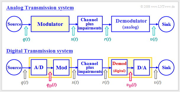
The diagram shows an analog transmission system at the top and a digital system drawn below. The main differences are highlighted in red:
While in the upper system the analog source signal $q(t)$ is applied to the modulator input, in the lower digital system the modulating signal $q_{\rm D}(t)$ is a digital signal, characterized by the amplitude coefficients $a_ν$, the basic pulse $g_q(t)$ and the symbol duration $T$:
- $$q_{\rm D}(t) = \sum_{\nu=-\infty}^{+\infty}a_\nu \cdot g_q(t - \nu \cdot T) \hspace{0.05cm}.$$
- The A/D conversion can be done for example by $\text{pulse code modulation}$ and includes the functions sampling, quantization, binary coding and signal shaping.
- The basic pulse $g_q(t)$ is often assumed to be NRZ-rectangular with amplitude $s_0$ and duration $T$. For the spectral function holds with ${\rm sinc}(x) = \sin(\pi x)/(\pi x)$:
- $$G_q(f) = s_0 · T · {\rm sinc}(f T).$$
- The modulators can be the same for both systems. They change one of the three signal parameters of the carrier $z(t)$ according to the modulator input. The digital variants of AM, PM, FM are called
- "Amplitude Shift Keying" $\rm (ASK)$,
- "Phase Shift Keying" $\rm (PSK)$,
- "Frequency Shift Keying" $\rm (FSK)$.
- In contrast, the demodulator of the digital system differs fundamentally from an analog demodulator by the required decision component (in hardware or software). Like $q_{\rm D}(t)$, the demodulator output signal $v_{\rm D}(t)$ is digital and must then be D/A converted into the analog sink signal $v(t)$.
- The decisive quality criterion for both systems is the $\text{sink SNR}$ ⇒ quotient of the power of source signal $q(t)$ and error signal $ε(t) = v(t) \ – \ q(t)$. In a digital system, one usually makes do with the quality characteristic $\text{bit error rate}$ $($ $\rm BER)$, which refers to the digital signals $q_{\rm D}(t)$ and $v_{\rm D}(t)$. This can be converted into a $\rm SNR$.
ASK – Amplitude Shift Keying
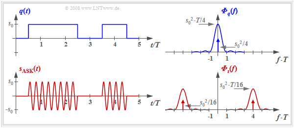
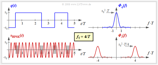
The diagram shows the digital source signal $q(t)$ – the index "D" is omitted from now on – and the ASK transmitted signal
- $$s_{\rm ASK}(t) = q(t) · \sin(2π · f_{\rm T} · t),$$
where unipolar amplitude coefficients $a_ν ∈ \{0, \ 1\}$ and a sinusoidal carrier (German: "Träger" ⇒ subscript "T") with frequency $f_{\rm T}$ are assumed here.
For example, this method is used in optical transmission systems (since there are no negative light pulses) and is also known as "On–Off–Keying".
In the right half of the figure, the corresponding power-spectral densities are shown - although not to scale.
With the rectangular basic pulse $g_q(t)$ and equally probable unipolar amplitude coefficients holds:
- $$\begin{align*}{{\it \Phi}_{q}(f)}& = \frac{{s_0}^2 \cdot T}{4} \cdot {\rm sinc}^2 (f T) + \frac{{s_0}^2 }{4} \cdot \delta (f)\hspace{0.05cm},\\ {{\it \Phi}_{s}(f)}& = \frac{1}{4} \cdot \big [ {{\it \Phi}_{q}(f- f_{\rm T})}+ {{\it \Phi}_{q}(f+ f_{\rm T})}\big]\hspace{0.05cm}.\end{align*}$$
It should be noted about these equations:
- The DC component $m_q = s_0/2$ of the source signal leads to a Dirac delta function at frequency $f = 0$ with weight ${s_0}^2/4$ in the power-spectral density $ϕ_q(f)$.
- The power-spectral density of the ASK transmitted signal $s(t)$ is equal to $ϕ_s(f) = ϕ_q(f) ∗ ϕ_z(f)$, where the PSD $ϕ_z(f)$ of the carrier $z(t)$ is composed of two Dirac delta functions at $±f_{\rm T}$ with respective weight $1/4$. The sign "$\star$" describes the convolution. The equation is also valid with other carrier phase.
- The power-spectral density $ϕ_s(f)$ is identical in shape to $ϕ_q(f)$ except for the shift by $±f_{\rm T}$ ⇒ the ASK belongs to the »linear digital modulation methods«.
Coherent demodulation of ASK signals
The diagram shows the block diagram of an ASK system including the receiver components.
- Let the source signal $q(t)$ be NRZ-rectangular and unipolar:
- $$a_ν ∈ \{0, \ 1\}.$$
- Let the channel be initially ideal, characterized by
- $$H_{\rm K}(f) = 1,\hspace{0.25cm} n(t) = 0 \hspace{0.5cm} \Rightarrow \hspace{0.5cm} r(t) = s(t).$$
The demodulation is performed coherently by means of a $\text{synchronous demodulator}$, the operation of which has already been described for the analog modulation methods AM and PM.
To summarize the block diagram:
- At the receiver the same carrier signal is added as at the transmitter, but with double amplitude.
- $z(t)$ denotes the carrier at the transmitter ⇒ the carrier at the receiver (German: "Empfänger" ⇒ subscript "E") is $z_{\rm E}(t) = 2 · z(t) $.
- Multiplication is followed by a suitably sized low-pass filter with frequency response $H_{\rm E}(f)$, which removes the higher frequency components of the signal $b(t)$.
- The detection signal $d(t)$ is sampled at instants $ν · T$ and decided using a threshold decision with threshold $E = {s_0}/2$.
- The sink signal $v(t)$ at the decision output is rectangular and in the noise-free case equal to the source signal $q(t)$ except for the transit time $T/2$.
$\text{To be noted:}$
- »Coherent demodulation« requires that the carrier frequency $f_{\rm T}$ and the carrier phase $ϕ_{\rm T}$ are exactly known to the receiver.
- The receiver must extract these two quantities from the received signal $r(t)$, which can be quite costly in the presence of strong channel distortion and large noise $n(t)$. Such realization aspects are dealt with, for example, in "Exercise 4.9" to this chapter.
- If the carrier phase $ϕ_{\rm T}$ is not known to the receiver, this is called »incoherent demodulation«, even if the carrier frequency $f_{\rm T}$ is known.
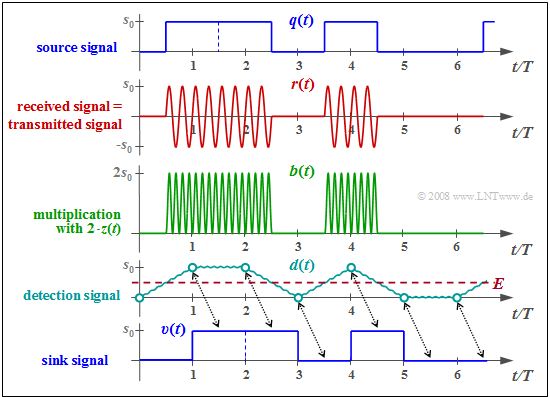
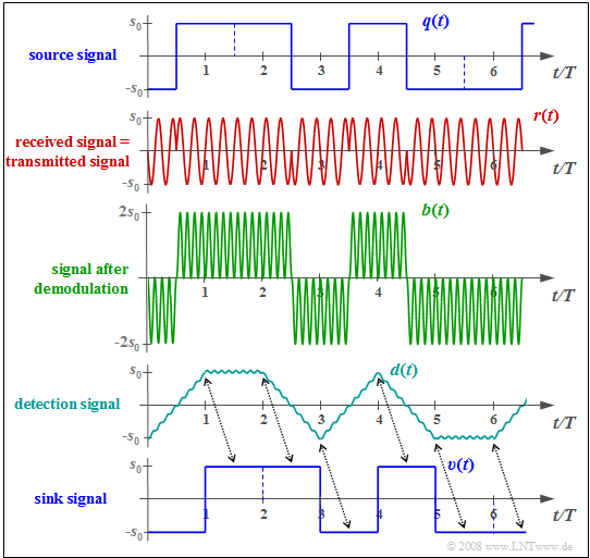
$\text{Example 1:}$ The diagram shows the signals mentioned in the ASK block diagram with ideal channel: $H_{\rm K}(f) = 1, \ \ n(t) = 0.$
The individual signal characteristics can be interpreted as follows:
- The transmitted signal $s(t)$ is the product of the unipolar source signal $q(t)$ and the carrier signal $z(t) = \sin(2π\hspace{0.05cm}f_{\rm T}\hspace{0.05cm}t)$, where in the example $f_{\rm T} = 4/T$ holds (only four oscillations per symbol duration).
- The received signal $r(t) = s(t)$ is first multiplied by the receiver-side carrier $z_{\rm E}(t) = 2 · \sin(2π\hspace{0.05cm}f_{\rm T}\hspace{0.05cm}t)$ ⇒ twice the amplitude compared to $z(t)$, no frequency and phase offset. This gives:
- $$b(t) = 2 \cdot z(t)\cdot r(t)= 2 \cdot z^2(t)\cdot q(t) $$
- $$\Rightarrow \hspace{0.35cm}b(t) = q(t) \cdot \big [ 1 - \cos(4\pi\hspace{0.05cm} f_{\rm T}\hspace{0.05cm} t)\big] \hspace{0.05cm}.$$
- The low-pass filter with frequency response $H_{\rm E}(f) = {\rm sinc}(f_{\rm T}\hspace{0.05cm} T)$ and corresponding rectangular impulse response $h_{\rm E}(t)$ forms from the signal $b(t)$ the detection signal $d(t) = b(t) \star h_{\rm E}(t)$ .
- $h_{\rm E}(t)$ is matched to the rectangular basic pulse $g_q(t)$. This is called the $\text{matched filter configuration}$ ⇒ best possible compromise between equalization and noise power limitation.
- In the absence of noise ⇒ $d(νT) = q(νT) ∈ \{0, \ s_0\}$. In the presence of (moderate) noise, it is very likely that $d(νT) > s_0/2,$ if $a_ν = +1$, and it will be $d(νT) < s_0/2$ for $a_ν = 0$.
- The decision obtains from the comparison of the samples $d(νT)$ with the threshold $E = s_0/2$ the sink signal $v(t)$, which is equal to $q(t)$ if the decision is error-free except for the transit time $T/2$.
Incoherent demodulation of ASK signals
We further assume ASK modulation as well as an ideal transmission channel, i.e.
- distortion-free,
- attenuation-free and
- noise-free.
Then applies: $r(t) = s(t) = q(t) \cdot \cos(2 \pi \cdot f_{\rm T} \cdot t + \phi_{\rm T})\hspace{0.05cm}.$
Further, it is assumed for this section
- that the receiver knows the carrier frequency $f_{\rm T}$,
- but not the carrier phase $ϕ_{\rm T}$.
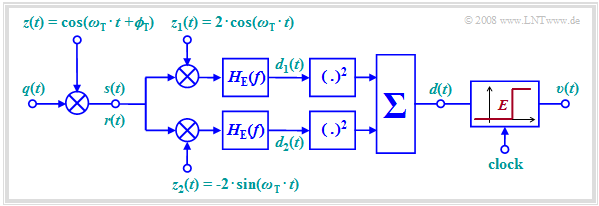
The diagram shows such an »incoherent demodulator« ⇒ the result of the demodulator is independent of the carrier phase $ϕ_{\rm T}$, which the receiver does not know.
The operation of this demodulator will be given here only as an outline:
- The signals $d_1(t)$ and $d_2(t)$ after the two $\text{matched filters}$ with respective frequency response $H_{\rm E}(f)$ are identical in shape to the detection signal $d(t)$ ⇒ $d_{\rm coh}(t)$ according to the $\text{previous block diagram}$, but generally attenuated with respect to it due to the lack of phase matching:
- $$d_1(t) = d_{\rm coh}(t) \cdot \cos( \phi_{\rm T}), \hspace{0.5cm}d_2(t) = -d_{\rm coh}(t) \cdot \sin( \phi_{\rm T}) \hspace{0.05cm}.$$
- If the amplitude coefficient is $a_ν = 0$, then in the noise-free case the two signal values are zero:
- $$d_1(ν · T) = 0,\hspace{0.5cm} d_2(ν · T) = 0.$$
- Otherwise $(a_ν = 1)$ applies:
- $$d_1(\nu \cdot T) = s_{\rm 0} \cdot \cos( \phi_{\rm T}), \hspace{0.5cm}d_2(\nu \cdot T) = -s_{\rm 0} \cdot \sin( \phi_{\rm T}) \hspace{0.05cm}.$$
- After squaring the two partial signals we get for the sum signal:
- $$d(\nu \cdot T) = \left\{ \begin{array}{c} 0 \\ {s^2_0} \end{array} \right.\quad \begin{array}{*{1}c} {\rm if}\hspace{0.15cm}a_\nu = 0, \\ {\rm if}\hspace{0.15cm}a_\nu = 1. \\ \end{array}$$
- By threshold decision – sensibly with the decision threshold $E = {s_0}^2/2$ – the amplitude coefficients $a_ν$ can be decided.
However in the noisy case, this results in a somewhat larger $\text{bit error probability}$ than with coherent demodulation.
BPSK – Binary Phase Shift Keying
For $\text{analog phase modulation}$ $\rm (PM)$, the transmitted signal is: $s_{\rm PM}(t) = s_0 \cdot \cos\big [2 \pi f_{\rm T} t + \phi_{\rm T}+
K_{\rm PM} \cdot q(t)\big ]\hspace{0.05cm}.$ With
- bipolar source signal ⇒ $a_ν ∈ \{-1, +1\}$,
- carrier phase $ϕ_{\rm T} = π \ (180^\circ)$
- modulator constant $K_{\rm PM} = π/(2s_0)$,
we obtain in the $ν$–th time interval:
- $$s_{\rm BPSK}(t) = \left\{ \begin{array}{c} s_0 \cdot \cos(2 \pi f_{\rm T} t + \pi+ \pi/2) \\ s_0 \cdot \cos(2 \pi f_{\rm T} t + \pi- \pi/2) \end{array} \right.\quad \begin{array}{*{1}c} {\rm if}\hspace{0.15cm}a_\nu = +1, \\ {\rm if}\hspace{0.15cm}a_\nu = -1. \\ \end{array}$$
This equation for »Binary Phase Shift Keying« $($ $\rm BPSK)$ can be transformed as follows:
- $$s_{\rm BPSK}(t) = a_\nu \cdot s_0 \cdot \sin(2 \pi f_{\rm T} t ) $$
- $$\Rightarrow \hspace{0.3cm}s_{\rm BPSK}(t) = \left\{ \begin{array}{c} s_0 \cdot \sin(2 \pi f_{\rm T} t ) \\ -s_0 \cdot \sin(2 \pi f_{\rm T} t ) \end{array} \right.\quad \begin{array}{*{1}c} {\rm if}\hspace{0.15cm}a_\nu = +1, \\ {\rm if}\hspace{0.15cm}a_\nu = -1. \\ \end{array}$$
In the diagram the signals and the corresponding power-spectral densities are sketched. It can be seen:
- Like the ASK signal, the BPSK signal can be represented as the product of the source signal $q(t)$ and the carrier signal $z(t)$. The only difference lies in the bipolar amplitude coefficients $a_ν ∈ \{-1, +1\}$ compared to the unipolar coefficients $(0$ or $1)$ with ASK.
- In contrast to ASK, with BPSK $($as with any form of phase modulation$)$ the envelope is constant. The information is transmitted here by the phase jumps within the transmitted signal $s(t)$ ⇒ gray backgrounds in the diagram.
- The power-spectral densities with BPSK differ from those with ASK only by the missing Dirac delta functions $($since now $q(t)$ does not contain a DC component$)$ and by the factor $4$ with respect to the continuous PSD components.
- It further follows that binary phase modulation $\rm (BPSK)$ can be counted as a linear modulation method. In general, (analog) phase modulation $\rm (PM)$ is, with a few exceptions, non-linear with respect to the source signal.
- For the diagrams, different carrier phases were chosen for display reasons in the section "ASK" ⇒ "sine" and here for "BPSK" ⇒ "minus cosine". However, this arbitrary determination is not a restriction. Both methods work in the same way for other carrier phases.
Demodulation and detection of BPSK signals
Due to the constant envelope of the BPSK signal, the demodulation must always be coherent here. The $\text{same block diagram}$ can be assumed as for coherent ASK demodulation.
$\text{Example 2:}$ The diagram shows from top to bottom
- the bipolar source signal $q(t)$,
- the received signal $r(t) = s(t)$ with ideal channel,
- $b(t)$ after multiplication by the receiver-side carrier $z_{\rm E}(t) = 2 \cdot z(t)$,
- the detection signal $d(t)$ after "integration" by the matched filter,
- the sink signal $v(t)$.
A comparison with the corresponding $\text{signals}$ in the coherent demodulation of the ASK shows:
- The rectangular signals $q(t)$ and $v(t)$ are now bipolar.
- For the detection signal at BPSK, compared to ASK, the following applies:
- $$d_{\rm BPSK}(t) =2 \cdot d_{\rm ASK}(t)-s_0.$$
- In the considered attenuation-free, distortion-free and noise-free case, all detection samples are $d(ν · T) = ±s_0$. Therefore, the decision threshold $E = 0$ should be used here.
- One can see the double distance of the BPSK detection samples (circle marks) from the threshold, which decisively improves $\text{error probability}$.
DPSK – Differential Phase Shift Keying
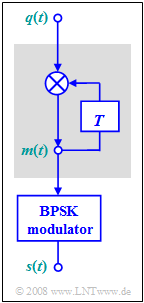
The diagram on the right shows the block diagram of the modulator for "Differential Phase Shift Keying" $\rm (DPSK)$.
- The bipolar source signal $q(t)$ with the amplitude coefficients $q_ν ∈ \{-1, +1\}$ is transformed according to this mapping into the signal $m(t)$ with the amplitude coefficients
- $$m_{\nu} = m_{\nu -1} \cdot q_{\nu} \in \{ -1, +1\}$$
- before it is fed to the BPSK modulator.
- If $q_ν = m_{ν-1}$, the mapped amplitude coefficient is $m_ν = +1$. In contrast, $m_ν = -1$ indicates that the amplitude coefficients $q_ν$ and $m_{ν-1}$ are different.
- An essential advantage of differential binary phase modulation is that the resulting signal $s(t)$ can be demodulated even without knowledge of the carrier phase $ϕ_{\rm T}$, see next section. Although the exact carrier frequency $f_{\rm T}$ must be known to the receiver, it is still referred to as an "incoherent PSK demodulator", and sometimes as a "differential coherent PSK demodulator".
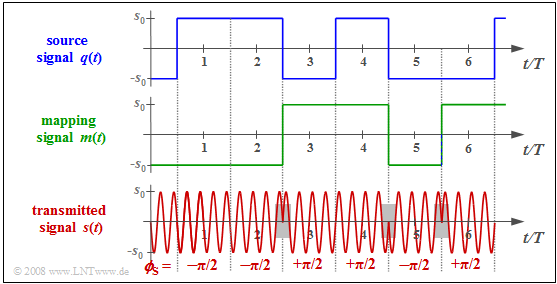
$\text{Example 3:}$ The diagram on the right shows
- the bipolar source signal $q(t)$,
- the mapping signal $m(t)$, and
- the DPSK transmitted signal $s(t)$.
In the following, $v_ν$ denotes the coefficients after the decision, which should coincide with the transmission-side amplitude coefficients $q_ν$.
The following principle can be seen:
- Whenever the receiver detects a phase jump, it decides $v_ν = -1$:
- $$v_3 = v_5 =v_6 =-1.$$
- If no phase jump is recognizable, $v_ν = +1$ is set:
- $$v_1 = v_2 =v_4 =+1.$$
Below the phase values $ϕ_{\rm S}$ are given for the first six symbols:
- Additional phase rotation on the channel, e.g. by $70.3π$, does change the absolute phase values to $69.8π$, $69.8π$, $70.8π$, $70.8π$, $69.8π$ and $70.8π$.
- However, the phase difference of adjacent symbols is preserved, so the differential coherent demodulation still works.
- A corresponding demodulator is presented in the following section.
Differential coherent demodulation of the DPSK signal
The graphic shows the block diagram of a transmission system with DPSK modulation ("Differential Phase Shift Keying") and differential coherent demodulation. In bullet point form, the given system can be described as follows:
- Ignoring the modulation with the carrier signals $z(t)$ and $2 · z(t)$ resp., the symbol $m_ν = m_{ν-1} · q_ν$ is present in the interval $ν$ at input (1) of the multiplier highlighted in yellow, and the symbol $m_{ν-1}$ is present at input (2).
- The multiplication of (1) and (2) gives the desired result:
- $$v_ν = m_{ν-1} · q_ν · m_{ν-1} = q_ν.$$
- It is taken into account here that $m_{ν-1} ∈ \{+1, –1\}$ holds.
- The matched filter with frequency response $H_{\rm E}(f)$ eliminates the unwanted components around the doubled carrier frequency $(\pm f_{\rm T})$ which result from the twofold multiplication by transmitter-side carrier $z(t)$ and receiver-side carrier $2 · z(t)$. With rectangular pulse $g_q(t)$ ⇒ $H_{\rm E}(f)$ can be realized by an integrator.
We now assume that the channel causes a phase rotation by $ϕ$, which the receiver does not know (red block):
- For example, assuming the transmitter-side carrier $z(t) = \cos (2π · f_{\rm T} · t)$, the received signal $r(t)$ contains a multiplicative component with $\cos (2π · f_{\rm T} · t + ϕ)$. Thus, the addition of the receiver-side carrier $2 · z(t)$ is not phase synchronous.
- The signal $r(t – T)$ delayed by a symbol duration $T$ has the same phase $ϕ$. The correlation between $2 · r(t) · z(t)$ and $2 · r(t – T) · z(t – T )$ makes the decision result independent of the random phase $ϕ$. This type of demodulation is called "differential-coherent".
Error probabilities - a brief overview
The error probabilities of the discussed digital modulation methods (ASK, BPSK, DPSK) are calculated in chapter "Linear Digital Modulation - Coherent Demodulation" of the book "Digital Signal Transmission" under different boundary conditions. Here only some results are given without proof, valid for
- a transmitted signal with the average energy $E_{\rm B}$ per bit,
- AWGN noise with the (one-sided) noise power density $N_0$, and
- best possible receiver realization using the matched filter principle.
$\text{Here without proof:}$ Let us first consider the »bit error probability« of $\text{Binary Phase Shift Keying}$ $\rm (BPSK)$ assuming a coherent receiver:
- $$p_{\text{B, BPSK, coh} } = {\rm Q}\left ( \sqrt{ {2 \cdot E_{\rm B} }/{N_0 } } \hspace{0.1cm}\right ) = {1}/{2}\cdot {\rm erfc}\left ( \sqrt{ {E_{\rm B} }/{N_0 } } \hspace{0.1cm}\right ).$$
- "Two variants of the complementary Gaussian error function" were used in the formulas:
- $${\rm Q} ({\it x}) = \frac{\rm 1}{\sqrt{\rm 2\pi} }\int_{\it x}^{+\infty}{\rm e}^{ {\it -u}^{\rm 2}/\rm 2}\,{\rm d} {\it u} \hspace{0.05cm},\hspace{0.3cm} {\rm erfc} ( {\it x} ) = \frac{\rm 2}{\sqrt{\rm \pi} }\int_{\it x}^{+\infty}{\rm e}^{ {\it -u}^{\rm 2} }\,{\rm d} {\it u} \hspace{0.05cm}.$$
- In contrast, for $\text{Amplitude Shift Keying}$ $\rm (ASK)$ with coherent demodulation:
- $$p_{\text{B, ASK, coh} } = {\rm Q}\left ( \sqrt{{E_{\rm B} }/{N_0 } } \hspace{0.1cm}\right ) ={1}/{2}\cdot {\rm erfc}\left ( \sqrt{ {E_{\rm B}}/{(2 \cdot N_0) } } \hspace{0.1cm}\right ).$$
- If we plot the bit error probability over the quotient $E_{\rm B}/N_0$ in double logarithmic scale, the ASK curve is always $3 \ \rm dB$ to the right of the BPSK curve. This degradation is one of the reasons why ASK is rarely used in practice.
- The decisive advantage of $\text{Differential Phase Shift Keying}$ $\rm (DPSK)$ is that it can be demodulated without knowledge of the carrier phase. This simple realization is bought by an increased error probability compared to coherent BPSK:
- $$p_{\text{B, DPSK, incoh} } = {1}/{2}\cdot {\rm e}^{ - {E_{\rm B} }/{N_0 } } .$$
- Incoherent demodulation of a BPSK signal, on the other hand, is not possible. For the $\text{incoherent ASK demodulation}$ one obtains:
- $$p_{\text{B, ASK, incoh} } = {1}/{2}\cdot {\rm e}^{- {E_{\rm B} }/{(2N_0) } } .$$
The equations given here are to be evaluated in "Exercise 4.8".
$\text{Example 4:}$
- For $\rm BPSK$ one needs $10 · \lg \ E_{\rm B}/N_0 ≈ 8.4 \ \rm dB$, to achieve the bit error probability $p_{\rm B} = \rm 10^{–4}$. However, this always requires coherent demodulation.
- With $($differential coherent$)$ $\rm DPSK$, about $9.3 \ \rm dB$ are necessary for this, i.e. almost one decibel more.
- With $\rm ASK$ one needs even $11.4 \ \rm dB$ $($with coherent demodulation$)$ or $12.3 \ \rm dB$ $($with incoherent demodulation$)$.
Exercises for the chapter
Exercise 4.7: Spectra of ASK and BPSK
Exercise 4.7Z: Signal Shapes for ASK, BPSK and DPSK
Exercise 4.8: Different Error Probabilities
Exercise 4.8Z: BPSK Error Probability
Exercise 4.9: Costas Rule Loop
