Contents
- 1 # OVERVIEW OF THE SECOND MAIN CHAPTER #
- 2 Source coding - Channel coding - Line coding
- 3 Lossy source encoding for images
- 4 Lossy source coding for audio signals
- 5 MPEG-2 Audio Layer III - short MP3
- 6 Description of lossless source encoding – Requirements
- 7 Kraft–McMillan inequality - Prefix-free codes
- 8 Source encoding theorem
- 9 Exercises for the chapter
# OVERVIEW OF THE SECOND MAIN CHAPTER #
Shannon's Information Theory is applied, for example, in the Source coding of digital (i.e. discrete-value and discrete-time) message sources. In this context, one also speaks of Data compression.
- Attempts are made to reduce the redundancy of natural digital sources such as measurement data, texts, or voice and image files (after digitization) by recoding them, so that they can be stored and transmitted more efficiently.
- In most cases, source encoding is associated with a change of the symbol set size. in the following, the output sequence is always binary.
The following is a detailed discussion:
- the different destinations of »source coding«, »channel coding« and »line coding«,
- »lossy encoding methods« for analog sources, for example GIF, TIFF, JPEG, PNG, MP3,
- the »source encoding theorem«, which specifies a limit for the average codeword length,
- the frequently used data compression according to »Lempel, Ziv and Welch«,
- the »Huffman code« as the best known and most efficient form of entropy coding,
- the »Shannon-Fano code« as well as the »arithmetic coding« - both belong to the class of entropy encoders as well,
- the »run-length encoding« and the »Burrows-Wheeler transformation« (BWT).
Source coding - Channel coding - Line coding
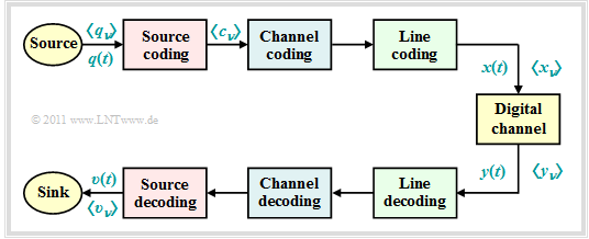
For the descriptions in this second chapter we consider the following model of a digital transmission system:
- The source signal $q(t)$ can be analog as well as digital, just like the sink signal $v(t)$. All other signals in this block diagram, even those not explicitly named here, are digital.
- In particular, also the signals $x(t)$ and $y(t)$ at the input and output of the "digital channel" are digital and can therefore also be described completely by the symbol sequences $〈x_ν〉$ and $〈y_ν〉$.
- The "digital channel" includes not only the transmission medium and interference (noise) but also components of the transmitter (modulator, transmitter pulse shaper, etc.) and the receiver (demodulator, receive filter, detector, decision maker).
- The chapter Parameters of Digital Channel Models in the book "Digital Signal Transmission" describes the modeling of the "digital channel".
As can be seen from this block diagram, there are three different types of coding, depending on the target direction. Each of which is realized by the "encoder" on the transmission side and the corresponding "decoder" at the receiver:
Task of the source coding is the reduction of redundancy for data compression, as it is used for example in image coding. By using correlations between the individual points of an image or between the brightness values of a pixel at different times (for moving picture sequences) procedures can be developed which lead to a noticeable reduction of the amount of data (measured in bit or byte) with nearly the same picture quality. A simple example is the »differential pulse code modulation« (DPCM).
With channel coding on the other hand, a noticeable improvement of the transmission behavior is achieved by using a redundancy specifically added at the transmitter to detect and correct transmission errors at the receiver side. Such codes, whose most important representatives are »block codes«, »convolutional codes« and »turbo codes«, are of great importance, especially for heavily disturbed channels. The greater the relative redundancy of the coded signal, the better the correction properties of the code, but at a reduced payload data rate.
Line coding is used to adapt the transmission signal $x(t)$ to the spectral characteristics of the channel and the receiving equipment by recoding the source symbols. For example, in the case of an (analog) transmission channel over which no direct signal can be transmitted, for which thus $H_{\rm K}(f = 0) = 0$, it must be ensured by line coding that the code symbol sequence does not contain long sequences of the same polarity.
The focus of this chapter is on lossless source coding, which generates a data-compressed code symbol sequence $〈c_ν〉$ starting from the source symbol sequence $〈q_ν〉$ and based on the results of information theory.
- Channel coding is the subject of a separate book in our tutorial with the following Content .
- The channel coding is discussed in detail in the chapter "Coded and multilevel transmission" of the book Digital Signal Transmission .
Note: We uniformly use "$\nu$" here as a control variable of a symbol sequence. Normally, for $〈q_ν〉$, $〈c_ν〉$ and $〈x_ν〉$ different indices should be used if the rates do not match.
Lossy source encoding for images
For digitizing analog source signals such as speech, music or pictures, only lossy source coding methods can be used. Even the storage of a photo in BMP-format is always associated with a loss of information due to sampling, quantization and the finite color depth.
However, there are also a number of compression methods for images that result in much smaller image files than "BMP", for example:
- GIF (Graphics Interchange Format ), developed by Steve Wilhite in 1987.
- JPEG - a format that was introduced in 1992 by the Joint Photography Experts Group and is now the standard for digital cameras. ending: "jpeg" or "jpg".
- TIFF (Tagged Image File Format), around 1990 by Aldus Corp. (now Adobe) and Microsoft, still the quasi-standard for print-ready images of the highest quality.
- PNG (Portable Network Graphics), designed in 1995 by T. Boutell & T. Lane as a replacement for the patent-encumbered GIF format, is less complex than TIFF.
These compression methods partly use
- Vector quantization for redundancy reduction of correlated pixels,
- at the same time the lossless compression algorithms according to Huffman and Lempel/Ziv,
- possibly also transformation coding based on DFT (Discrete Fourier Transformation ) and DCT (Discrete Cosine Transformation ),
- then quantization and transfer in the transformed range.
We now compare the effects of two compression methods on the subjective quality of photos and graphics, namely:
- JPEG $($with compression factor $8)$, and
- PNG $($with compression factor $24)$.
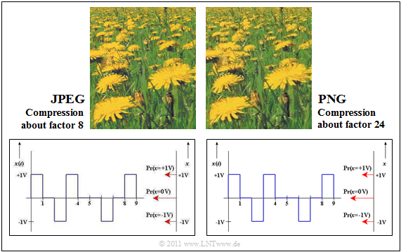
$\text{Example 1:}$ In the upper part of the following figure you can see two compressions of a photo.
The format JPEG (left image) allows a compression factor of $8$ to $15$ with (nearly) lossless compression.
- Even with the compression factor $35$ the result can still be called "good".
- For most consumer digital cameras, "JPEG" is the default storage format.
The image shown on the right was compressed with PNG .
- The quality is similar to the left JPEG image, although the compression is about $3$ stronger.
- In contrast, PNG achieves a worse compression result than JPEG if the photo contains a lot of color gradations.
PNG is also better suited for line drawings with captions than JPEG (lower images). The quality of the JPEG compression (left) is significantly worse than the PNG result, although the resulting file size is about three times as large. Especially fonts look "washed out".
Note: Due to technical limitations of $\rm LNTww$ all graphics had to be saved as "PNG".
- In the above graphic, "JPEG" means the PNG conversion of a file previously compressed with "JPEG".
- However, the associated loss is negligible.
Lossy source coding for audio signals
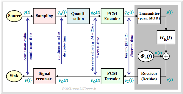
A first example of source coding for speech and music is the Pulse-code modulation (PCM), invented in 1938, which extracts the code symbol sequence $〈c_ν〉 $ from an analog source signal $q(t)$, corresponding to the three processing blocks
- Sampling,
- Quantization, and
- PCM encoding.
The graphic illustrates the PCM principle. A detailed description of the picture can be found on the first pages of the chapter Pulse Code Modulation in the book "Modulation Methods".
Because of the necessary band limitation and quantization, this transformation is always lossy. That means
- The code sequence $〈c_ν〉$ has less information than the signal $q(t)$.
- The sink signal $v(t)$ is fundamentally different from $q(t)$.
- Mostly, however, the deviation is not very large.
We will now mention two transmission methods based on pulse code modulation as examples.
{{GraueBox|TEXT= $\text{Example 2:}$ The following data is taken from the GSM-Specification :
- If a speech signal is spectrally limited to the bandwidth $B = 4 \, \rm kHz$ ⇒ sampling rate $f_{\rm A} = 8 \, \rm kHz$ with a quantization of $13 \, \rm Bit$ ⇒ number of quantization levels $M = 2^{13} = 8192$ a binary data stream of data rate $R = 104 \, \rm kbit/s$ results.
- The quantization noise ratio is then $20 - \lg M ≈ 78 \, \rm dB$.
- For quantization with $16 \, \rm Bit$ this increases to $96 \, \rm dB$. At the same time, however, the required data rate increases to $R = 128 \, \rm kbit/s$.
The interactive applet Impact of a Bandwidth Limitation for Speech and Music illustrates the effects of a bandwidth limitation.}
$\text{Example 3:}$ The standard ISDN (Integrated Services Digital Network ) for telephony via two-wire line is also based on the PCM principle, whereby each user is assigned two B-channels (Bearer Channels ) with $64 \, \rm kbit/s$ ⇒ $M = 2^{8} = 256$ and a D-channel (Data Channel ) with $ 16 \, \rm kbit/s$.
- The net data rate is thus $R_{\rm net} = 144 \, \rm kbit/s$.
- In consideration of the channel coding and the control bits (required for organizational reasons), the ISDN gross data rate of $R_{\rm gross} = 192 \, \rm kbit/s$.
In mobile communications, very high data rates often could not (yet) be handled. In the 1990s, voice coding procedures were developed that led to data compression by the factor $8$ and more. From today's point of view, it is worth mentioning
- the Enhanced Full-Rate Codec (EFR), which extracts exactly $244 \, \rm Bit$ for each speech frame of $20\, \rm ms$ $($Data rate: $12. 2 \, \rm kbit/s)$;
this data compression of more than the factor $8$ is achieved by stringing together several procedures:
- Linear Predictive Coding (LPC, short term prediction),
- Long Term Prediction (LTP, long term prediction) and
- Regular Pulse Excitation (RPE');
- the Adaptive Multi-Rate Codec (AMR) based on ACELP (Algebraic Code Excited Linear Prediction) and several modes between $12. 2 \, \rm kbit/s$ (EFR) and $4.75 \, \rm kbit/s$ so that improved channel coding can be used in case of poorer channel quality;
- the Wideband-AMR (WB-AMR) with nine modes between $6.6 \, \rm kbit/s$ and $23.85 \, \rm kbit/s$. This is used with UMTS and is suitable for broadband signals between $200 \, \rm Hz$ and $7 \, \rm kHz$ . Sampling is done with $16 \, \rm kHz$, quantization with $4 \, \rm Bit$.
All these compression methods are described in detail in the chapter Voice Coding of the book "Examples of Communication Systems" The Audio Module Quality of different voice codecs (Applet) allows a subjective comparison of these codecs.
MPEG-2 Audio Layer III - short MP3
Today (2015) the most common compression method for audio files is MP3. This format was developed from 1982 on at the Fraunhofer Institute for Integrated Circuits (IIS) in Erlangen under the direction of Prof. org/wiki/Hans-Georg_Musmann Hans-Georg Musmann in collaboration with the Friedrich Alexander University Erlangen-Nuremberg and AT&T Bell Labs. Other institutions are also asserting patent claims in this regard, so that since 1998 various lawsuits have been filed which, to the authors' knowledge, have not yet been finally concluded.
In the following some measures are called, which are used with MP3, in order to reduce the data quantity in relation to the raw version in the WAV-format. The compilation is not complete. A comprehensive representation about this can be found for example in a Wikipedia article.
- The audio compression method "MP3" uses among other things psychoacoustic effects of perception. So a person can only distinguish two sounds from each other from a certain minimum difference in pitch. One speaks of so-called "masking effects".
- Using the masking effects, MP3 signals that are less important for the auditory impression are stored with less bits (reduced accuracy). A dominant tone at $4 \, \rm kHz$ can, for example, cause neighboring frequencies to be of only minor importance for the current auditory sensation up to $11 \, \rm kHz$ .
- The greatest saving of MP3 coding, however, is that the sounds are stored with just enough bits so that the resulting Quantization Noise is still masked and is not audible.
- Other MP3 compression mechanisms are the exploitation of the correlations between the two channels of a stereo signal by difference formation as well as the Huffman Coding of the resulting data stream. Both measures are lossless.
A disadvantage of the MP3 coding is that with strong compression also "important" frequency components are unintentionally captured and thus audible errors occur. Furthermore it is disturbing that due to the blockwise application of the MP3 procedure gaps can occur at the end of a file. A remedy is the use of the so-called LAME-Coder, an Open Source Project, and a corresponding player.
Description of lossless source encoding – Requirements
In the following, we only consider lossless source coding methods and make the following assumptions:
- The digital source has the symbol range $M$. For the individual source symbols of the sequence $〈q_ν〉$ applies with the symbol range $\{q_μ\}$:
- $$q_{\nu} \in \{ q_{\mu} \}\hspace{0.05cm}, \hspace{0.2cm}\mu = 1, \hspace{0.05cm}\text \hspace{0.05cm}, M \hspace{0.05cm}. $$
The individual sequence elements $q_ν$ may be statistically independent or may have statistical bonds;
- First we consider message sources without memory, which are fully characterized by symbol probabilities alone, for example:
$$M = 4\text{:} \ \ \ q_μ \in \{ {\rm A}, \ {\rm B}, \ {\rm C}, \ {\rm D} \}, \hspace{2.5cm} \text{with the probabilities}\ p_{\rm A},\ p_{\rm B},\ p_{\rm C},\ p_{\rm D},$$
- $$M = 8\text{:} \ \ \ q_μ \in \{ {\rm A}, \ {\rm B}, \ {\rm C}, \ {\rm D},\ {\rm E}, \ {\rm F}, \ {\rm G}, \ {\rm H} \}, \hspace{0.5cm} \text{with the probabilities }\ p_{\rm A},\hspace{0.05cm}\text{...} \hspace{0.05cm} ,\ p_{\rm H}.$$
- The source encoder replaces the source symbol $q_μ$ with the code word $\mathcal{C}(q_μ)$, consisting of $L_μ$ code symbols of a new alphabet with the symbol range $D$ $\{0, \ 1$, ... , $D - 1\}$. This gives the average code word length:
- $$L_{\rm M} = \sum_{\mu=1}^{M} \hspace{0.1cm} p_{\mu} \cdot L_{\mu} \hspace{0.05cm}, \hspace{0.2cm}{\rm mit} \hspace{0.2cm}p_{\mu} = {\rm Pr}(q_{\mu}) \hspace{0.05cm}. $$
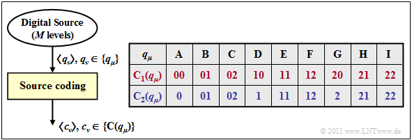
$\text{Example 4:}$ We consider two different types of source encoding, each with the parameters $M = 9$ and $D = 3$.
- In the first encoding $\mathcal{C}_1(q_μ)$ according to line 2 (red) of the lower table, each source symbol $q_μ$ is replaced by two ternary symbols $(0$, $1$ or $2)$ For example, the mapping:
- $$\rm A C F B I G \ ⇒ \ 00 \ 02 \ 12 \ 01 \ 22 \ 20.$$
- With this coding, all code words have $\mathcal{C}_1(q_μ)$ with $1 ≤ μ ≤ 6$ the same length $L_μ = 2$. Thus, the average code word length $L_{\rm M} = 2$.
- The second, the blue source coder $L_μ ∈ \{1, 2 \}$ and accordingly, the average code word length $L_{\rm M}$ will be less than two code symbols per source symbol. Here we have for example this mapping:
- $$\rm A C F B I G \ ⇒ \ 0 \ 02 \ 12 \ 01 \ 22 \ 2.$$
- It is obvious that this second code symbol sequence cannot be decoded unambiguously, since the symbol sequence naturally does not include the spaces inserted in this text for display reasons.
Kraft–McMillan inequality - Prefix-free codes
Binary codes for compressing a memoryless value discrete source are characterized by the fact that the individual symbols are represented by code symbol sequences of different lengths:
- $$L_{\mu} \ne {\rm const.} \hspace{0.4cm}(\mu = 1, \hspace{0.05cm}\text{...} \hspace{0.05cm}, M ) \hspace{0.05cm}.$$
Only then it is possible,
- that the average code word length becomes minimal ,
- if the source symbols are not equally probable are
To enable a unique decoding, the code must also be "prefix-free".
$\text{Definition:}$ The property prefix-free indicates that no codeword may be the prefix (beginning) of a longer codeword. Such a codeword is immediately decodable.
- The blue code in the Example 4 is not prefix-free. For example, the code symbol sequence "01" could be interpreted by the decoder as $\rm AD$ but also as $\rm B$.
- The red code, on the other hand, is prefix-free, although prefix freedom would not be absolutely necessary here because of $L_μ = \rm const.$ .
$\text{Without proof:}$ The necessary Condition for the existence of a prefix-free code was specified by Leon Kraft in his master thesis 1949 at Massachusetts Institute of Technology (MIT) :
- $$\sum_{\mu=1}^{M} \hspace{0.2cm} D^{-L_{\mu} \le 1 \hspace{0.05cm}.$$
$\text{Example 5:}$ If you check the second (blue) code of Example 4 with $M = 9$ and $D = 3$, you get:
- $$3 \cdot 3^{-1} + 6 \cdot 3^{-2} = 1.667 > 1 \hspace{0.05cm}.$$
From this you can see that this code cannot be prefix-free
$\text{Example 6:}$ Let's look at the binary code
- $$\boldsymbol{\rm A } \hspace{0.15cm} \Rightarrow \hspace{0.15cm} 0 \hspace{0.05cm}, \hspace{0.2cm}\boldsymbol{\rm B } \hspace{0.15cm} \Rightarrow \hspace{0.15cm} 00 \hspace{0.05cm}, \hspace{0.2cm}\boldsymbol{\rm C } \hspace{0.15cm} \Rightarrow \hspace{0.15cm} 11 \hspace{0.05cm}, $$
it is obviously not prefix-free. The equation
- $$1 \cdot 2^{-1} + 2 \cdot 2^{-2} = 1 $$
does not mean that this code is actually prefix-free, it just means that there is a prefix-free code with the same length distribution, for example
- $$\boldsymbol{\rm A } \hspace{0.15cm} \Rightarrow \hspace{0.15cm} 0 \hspace{0.05cm}, \hspace{0.2cm}\boldsymbol{\rm B } \hspace{0.15cm} \Rightarrow \hspace{0.15cm} 10 \hspace{0.05cm}, \hspace{0.2cm}\boldsymbol{\rm C } \hspace{0.15cm} \Rightarrow \hspace{0.15cm} 11 \hspace{0.05cm}.$$
Source encoding theorem
We now look at a redundant message source with the symbol set $〈q_μ〉$, where the control variable $μ$ takes all values between $1$ and the symbol range $M$. The source entropy $H$ is smaller than the message content $H_0$.
The redundancy $(H_0- H)$ is either caused by
- not equally probable symbols ⇒ $p_μ ≠ 1/M$, and/or
- statistical bonds within the sequence $〈q_\nu〉$.
A source encoder replaces the source symbol $q_μ$ with the binary codeword $\mathcal{C}(q_μ)$, consisting of $L_μ$ binary symbols (zeros or ones). This results in an average codeword length:
- $$L_{\rm M} = \sum_{\mu=1}^{M} \hspace{0.2cm} p_{\mu} \cdot L_{\mu} \hspace{0.05cm}, \hspace{0.2cm}{\rm mit} \hspace{0.2cm}p_{\mu} = {\rm Pr}(q_{\mu}) \hspace{0.05cm}. $$
For the source encoding task described here the following limit can be specified:
$\text{Theorem:}$ For the possibility of a complete reconstruction of the sent string from the binary sequence it is sufficient, but also necessary, that
- for encoding on the transmitting side at least $H$ binary symbols per source symbol are used.
- the average code word length $L_{\rm M}$ cannot be smaller than the entropy $H$ of the source symbol sequence:
- $$L_{\rm M} \ge H \hspace{0.05cm}. $$
This regularity is called Source Coding Theorem, which goes back to Claude Elwood Shannon If the source coder considers only the different probabilities of occurrence, but not the inner statistical bonds of the sequence, then $L_{\rm M} ≥ H_1$ ⇒ first Entropy Approximation.
$\text{Example 7:}$ For a quaternary source with the symbol probabilities
- $$p_{\rm A} = 2^{-1}\hspace{0.05cm}, \hspace{0.2cm}p_{\rm B} = 2^{-2}\hspace{0.05cm}, \hspace{0.2cm}p_{\rm C} = p_{\rm D} = 2^{-3} \hspace{0.3cm} \Rightarrow \hspace{0.3cm} H = H_1 = 1.75\,\, {\rm bit/source symbol} $$
equality in the above equation ⇒ $L_{\rm M} = H$ results, if for example the following assignment is chosen
- $$\boldsymbol{\rm A } \hspace{0.15cm} \Rightarrow \hspace{0.15cm} 0 \hspace{0.05cm}, \hspace{0.2cm}\boldsymbol{\rm B } \hspace{0.15cm} \Rightarrow \hspace{0.15cm} 10 \hspace{0.05cm}, \hspace{0.2cm}\boldsymbol{\rm C} \hspace{0.15cm} \Rightarrow \hspace{0.15cm} 110 \hspace{0.05cm}, \hspace{0.2cm}\boldsymbol{\rm D }\hspace{0.15cm} \Rightarrow \hspace{0.15cm} 111 \hspace{0.05cm}. $$
In contrast, with the same mapping and
- $$p_{\rm A} = 0.4\hspace{0.05cm}, \hspace{0.2cm}p_{\rm B} = 0.3\hspace{0.05cm}, \hspace{0.2cm}p_{\rm C} = 0.2 \hspace{0.05cm}, \hspace{0.2cm}p_{\rm D} = 0.1\hspace{0.05cm} \hspace{0.3cm} \Rightarrow \hspace{0.3cm} H = 1.845\,\, {\rm bit/source symbol}$$
the average code word length
- $$L_{\rm M} = 0.4 \cdot 1 + 0.3 \cdot 2 + 0.2 \cdot 3 + 0.1 \cdot 3 = 1.9\,\, {\rm bit/source symbol}\hspace{0.05cm}. $$
Because of the unfavorably chosen symbol probabilities (no powers of two) $L_{\rm M} > H$.
$\text{Example 8:}$ We will look at some very early attempts at source encoding for the transmission of natural texts, based on the letter frequencies given in the table.
- In the literature many different frequencies are found, also because, the investigations were carried out for different languages.
- Mostly, however, the list starts with the blank and "E" and ends with letters like "X", "Y" and "Q".
Please note the following about this table:
- The entropy of this alphabet with $M = 27$ character will be $H≈ 4 \, \rm bit/character$ is We have not recalculated this. Francis Bacon had already given a binary code in 1623, where each letter is represented by five bits: $L_{\rm M} = 5$.
- About 250 years later Jean-Maurice-Émile Baudot adopted this code, which was later standardized for the entire telegraphy. One consideration important to him was that a code with a uniform five binary characters per letter is more difficult for an enemy to decipher, since he cannot draw conclusions about the transmitted character from the frequency of its occurrence.
- The last line in the above table gives an exemplary Huffman-Code for the above frequency distribution. Probable characters like "E" or "N" and also the "Blank" are represented with only three bits, the rare "Q" on the other hand with $11$ bit.
- The average code word length $L_{\rm M} = H + ε$ is slightly larger than $H$, whereby we will not go into more detail here about the small positive size $ε$ Only this much: There is no prefix-free code with smaller average word length than the Huffman code.
- Also Samuel Morse took into account the different frequencies in his code for telegraphy, already in the 1830s. The Morse code of each character consists of two to four binary characters, which are designated here according to the application with dot ("short") and bar ("long").
- It is obvious that for the Morse code $L_{\rm M} < 4$ will apply, according to the penultimate line. But this is connected with the fact that this code is not prefix-free. Therefore, the radio operator had to take a break between each short-long sequence so that the other station could decode the radio signal as well.
Exercises for the chapter
Aufgabe 2.1: Codierung mit und ohne Verlust
Aufgabe 2.2: Kraftsche Ungleichung
Aufgabe 2.2Z: Mittlere Codewortlänge


