Contents
- 1 # OVERVIEW OF THE THIRD MAIN CHAPTER #
- 2 Prerequisites for the entire "realizable systems" chapter
- 3 Real and imaginary part of a causal transfer function
- 4 Hilbert transformation
- 5 Some pairs of Hilbert correspondences
- 6 Attenuation and phase of minimum-phase systems
- 7 Exercises for the chapter
- 8 List of sources
# OVERVIEW OF THE THIRD MAIN CHAPTER #
In the first two chapters, filter functions with real-valued frequency responses were mostly considered for reasons of presentation so that the associated time function is symmetric about zero-time. However, the impulse response of a realisable system must always be causal, that is, $h(t)$ must be identical to zero for $t < 0$ . This strong asymmetry of the time function $h(t)$, though, implies at the same time that the frequency response $H(f)$ of a realisable system is always complex-valued with the exception of $H(f) = K$ where there is a fixed relation between its real part and imaginary part.
This third chapter provides a recapitulatory account of the description of causal realizable systems, which differ also in the mathematical methods from those commonly used with non-causal systems.
In detail, the following is dealt with:
- the Hilbert transformation, which states how real and imaginary parts of $H(f)$ are related,
- the Laplace transformation, which yields another spectral function $H_{\rm L}(p)$ for causal $h(t)$ ,
- the description of realizable systems by the pole-zero plot, as well as
- the inverse Laplace transformation using the theory of functions (residue theorem).
For this chapter we recommend
- the educational video Arithmetic with complex numbers for preparation, as well as
- the interactive applet Causal systems – Laplace transformation - a coherent depiction.
Prerequisites for the entire "realizable systems" chapter
In the first two chapters, mostly real transfer functions $H(f)$ were considered for which the associated impulse response $h(t)$ is consequently always symmetric with respect to the reference time $t = 0$ . Such transfer functions
- are suitable to explain basic relationships in a simple way,
- but unfortunately are not realizable for reasons of causality.
This becomes clear if the definition of the impulse response is considered:
$\text{Definition:}$ The impulse response $h(t)$ is equal to the output signal $y(t)$ of the system if an infinitely short impulse with an infinitely large amplitude is applied to the input at time $t = 0$ : $x(t) = δ(t)$. Such an impulse is called a Dirac impulse.
It is obvious that no impulse response can be realized for which $h(t < 0) ≠ 0$ holds.
$\text{Definition:}$ For a causal system the impulse response $h(t)$ is identical to zero for all times $t < 0$ .
The only real transfer function that satisfies the causality condition "the output signal cannot start before the input signal" is:
- $$H(f) = K \quad \bullet\!\!-\!\!\!-\!\!\!-\!\!\circ\quad h(t) = K \cdot \delta(t).$$
All other real-valued transfer functions $H(f)$ describe non-causal systems and thus cannot be realized by an (electrical) circuit network.
$\text{In other words:}$ Except for the transfer function $H(f) = K,$ any realistic transfer function is complex.
- If $K=1$ holds additionally, the transfer function is said to be ideal.
- The output $y(t)$ is then identical to the input $x(t)$ – even without attenuation or amplification.
Real and imaginary part of a causal transfer function
Any causal impulse response $h(t)$ can be represented as the sum of an even part $h_{\rm g}(t)$ and an odd part $h_{\rm u}(t)$ :
- $$\begin{align*} h_{ {\rm g}}(t) & = {1}/{2}\cdot \big[ h(t) + h(-t) \big]\hspace{0.05cm},\\ h_{ {\rm u}}(t) & = {1}/{2}\cdot \big[ h(t) - h(-t) \big] = h_{ {\rm g}}(t) \cdot {\rm sign}(t)\hspace{0.05cm} .\end{align*}$$
Here, the so-called sign function is used:
- $${\rm sign}(t) = \left\{ \begin{array}{c} -1 \\ +1 \\ \end{array} \right.\quad \quad \begin{array}{c} {\rm{for}} \\ {\rm{for}} \\ \end{array}\begin{array}{*{20}c} { t < 0,} \\ { t > 0.} \\ \end{array}$$
$\text{Example 1:}$ The graph shows this splitting for a causal exponentially decreasing impulse response of a low-pass filter of first-order corresponding to Exercise 1.3Z:
- $$h(t) = \left\{ \begin{array}{c} 0 \\ 0.5/T \\ 1/T \cdot {\rm e}^{-t/T} \end{array} \right.\quad \begin{array}{c} {\rm{f\ddot{u}r} } \\ {\rm{f\ddot{u}r} } \\ {\rm{f\ddot{u}r} } \end{array}\begin{array}{*{20}c} { t < 0\hspace{0.05cm},} \\ { t = 0\hspace{0.05cm},} \\{ t > 0\hspace{0.05cm}.} \end{array}$$
It can be seen that:
- $h_{\rm g}(t) = h_{\rm u}(t) = h(t)/2$ holds for positive times.
- $h_{\rm g}(t)$ and $h_{\rm u}(t)$ differ only by the sign for negative times.
- $h(t) = h_{\rm g}(t) + h_{\rm u}(t)$ holds for all times, also at time $t = 0$ (marked by circles).
Let us now consider the same issue in the spectral domain. According to the Assignment Theorem the following holds for the complex transfer function:
- $$H(f) = {\rm Re} \left\{ H(f) \right \} + {\rm j} \cdot {\rm Im} \left\{ H(f) \right \} ,$$
where the following assignment holds:
- $${\rm Re} \left\{ H(f) \right \} \quad \bullet\!\!-\!\!\!-\!\!\!-\!\!\circ\quad h_{ {\rm g}}(t)\hspace{0.05cm},$$
- $${\rm j} \cdot {\rm Im} \left\{ H(f) \right\} \quad \bullet\!\!-\!\!\!-\!\!\!-\!\!\circ\quad h_{ {\rm u}}(t)\hspace{0.05cm}.$$
First, this relationship between the real and imaginary parts of $H(f)$ shall be worked out using another example.
$\text{Example 2:}$ A low-pass filter of first-order is assumed and the following holds for its transfer function:
- $$H(f) = \frac{1}{1+{\rm j}\cdot f/f_{\rm G} } = \frac{1}{1+(f/f_{\rm G})^2}- {\rm j} \cdot \frac{f/f_{\rm G} }{1+(f/f_{\rm G})^2} \hspace{0.05cm}.$$
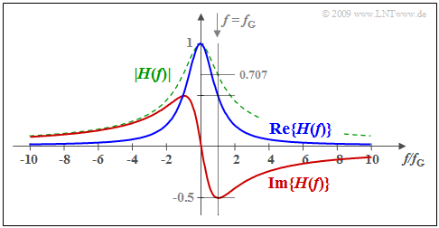
Here, $f_{\rm G}$ represents the 3dB cut-off frequency at which $\vert H(f)\vert^2$ has decreased to half of its maximum $($at $f = 0)$ . The corresponding impulse response $h(t)$ has already been shown in the above $\text{Example 1}$ for $f_{\rm G} = 1/(2πT)$ .
The graph shows the real part (blue) and the imaginary part (red) of $H(f)$. In addition, the magnitude is shown dashed in green.
Since the time functions $h_{\rm g}(t)$ and $h_{\rm u}(t)$ are related by the sign function, there also exists a fixed relationship
- between the real part ⇒ ${\rm Re} \{H(f)\}$
- and the imaginary part ⇒ ${\rm Im} \{H(f)\}$
of the transfer function
⇒ the Hilbert transformation.
This is described below.
Hilbert transformation
Here, two time functions $u(t)$ and $w(t) = \sign(t) · u(t)$ are considered in the most general sense.
- The associated spectral functions are denoted by $U(f)$ and ${\rm j} · W(f)$ .
- That is, in this section ${w(t) \, \circ\!\!-\!\!\!-\!\!\!-\!\!\bullet \, {\rm j} \cdot W(f) }$ is valid and not the usual Fourier correspondence ${w(t) \, \circ\!\!-\!\!\!-\!\!\!-\!\!\bullet \, W(f)}.$
Using the correspondence ${\rm sign}(t) \, \circ\!\!-\!\!\!-\!\!\!-\!\!\bullet \, {1}/({{\rm j} \, \pi f })$ the following is obtained after writing the convolution integral out in full with the integration variable $ν$ :
- $${\rm j} \cdot W(f) = \frac{1}{{\rm j} \, \pi f }\, \star \, U(f) \quad \Rightarrow \quad W(f) = -\frac{1}{\pi }\int\limits_{-\infty}^{+\infty} { \frac{U(\nu)}{f - \nu}}\hspace{0.1cm}{\rm d}\nu \hspace{0.05cm}.$$
However, since at the same time $u(t) = \sign(t) · w(t)$ also holds, the following is valid in the same way:
- $$U(f) = \frac{1}{{\rm j} \, \pi f }\, \star \, {\rm j} \cdot W(f) \quad \Rightarrow \quad U(f) = \frac{1}{\pi }\int\limits_{-\infty}^{+\infty} { \frac{W(\nu)}{f - \nu}}\hspace{0.1cm}{\rm d}\nu \hspace{0.05cm}.$$
These integral transformations are named after their discoverer David Hilbert .
$\text{Definition:}$ Both variants of the Hilbert transformation will be denoted by the following abbreviations in the further course:
- $$W(f) \quad \bullet\!\!-\!\!\!-\!\!\!-\!\!\hspace{-0.05cm}\rightarrow\quad U(f) \hspace{0.8cm}{\rm or}\hspace{0.8cm}W(f)= {\cal H}\left\{U(f) \right \}\hspace{0.05cm}.$$
- To calculate the spectrum marked by the arrowhead – here $U(f)$ – the equation with the positive sign is taken from the two otherwise identical upper equations:
- $$U(f) = \frac{1}{\pi }\int\limits_{-\infty}^{+\infty} { \frac{W(\nu)}{f - \nu} }\hspace{0.1cm}{\rm d}\nu \hspace{0.05cm}.$$
- The spectrum marked by the circle – here $W(f)$ – arises as a result from the equation with the negative sign:
- $$ W(f) = -\frac{1}{\pi }\int\limits_{-\infty}^{+\infty} { \frac{U(\nu)}{f - \nu} }\hspace{0.1cm}{\rm d}\nu \hspace{0.05cm}.$$
Applying the Hilbert transformation twice yields the original function with a change of sign, and applying it four times yields the original function including the correct sign:
- $${\cal H}\left\{ {\cal H}\left\{ U(f) \right \} \right \} = -U(f), \hspace{0.2cm} {\cal H}\left\{ {\cal H}\left\{ {\cal H}\left\{ {\cal H}\left\{ U(f) \right \} \right \} \right \} \right \}= U(f)\hspace{0.05cm}.$$
$\text{Example 3:}$ In [Mar94][1] the following Hilbert correspondence can be found:
- $$\frac{1}{1+x^2} \quad \bullet\!\!-\!\!\!-\!\!\!-\!\!\hspace{-0.05cm}\rightarrow\quad \frac{x}{1+x^2}\hspace{0.05cm}.$$
- Here $x$ is representative of a suitably normalized time or frequency variable.
- For example, if we use $x = f/f_{\rm G}$ as a normalized frequency variable, then we obtain the correspondence:
- $$\frac{1}{1+(f/f_{\rm G})^2} \quad \bullet\!\!-\!\!\!-\!\!\!-\!\!\hspace{-0.05cm}\rightarrow\quad \frac{f/f_{\rm G} }{1+(f/f_{\rm G})^2}\hspace{0.05cm}.$$
Based on the equation
- $${\rm Im} \left\{ H(f) \right \} \quad \bullet\!\!-\!\!\!-\!\!\!-\!\!\hspace{-0.05cm}\rightarrow\quad {\rm Re} \left\{ H(f) \right \}$$
the result found in $\text{Example 2}$ is thus confirmed:
- $${\rm Im} \left\{ H(f) \right \} = \frac{-f/f_{\rm G} }{1+(f/f_{\rm G})^2}\hspace{0.05cm}.$$
Some pairs of Hilbert correspondences
A very pragmatic way is followed to derive Hilbert correspondences, namely as follows:
- The Laplace transform $Y_{\rm L}(p)$ of the function $y(t)$ is computed as described below. This is already implicitly causal.
- The spectral function $Y_{\rm L}(p)$ is converted into the associated Fourier spectrum $Y(f)$ which is split it into real and imaginary parts. To do this, the variable $p$ is replaced by ${\rm j \cdot 2}πf.$
- The real– and imaginary parts – so ${\rm Re} \{Y(f)\}$ and ${\rm Im} \{Y(f)\}$ – are thus a pair of Hilbert transforms. Furthermore,
- the frequency variable $f$ is substituted by $x$,
- ${\rm Re} \{Y(f)\}$ by $g(x)$, and
- ${\rm Im} \{Y(f)\}$ by ${\cal H} \{g(x)\}$.
- The new variable $x$ can describe both a (suitably) normalized frequency or a (suitably) normalized time. Hence, the Hilbert transformation is applicable to various problems.
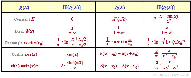
The table shows some of such Hilbert pairs. The signs have been omitted so that both directions are valid.
$\text{Example 4:}$ For example, if ${\cal H} \{g(x)\} = f(x)$ holds, then from this it also follows that ${\cal H} \{f(x)\} = \, –g(x)$. In particular, it also holds:
- $${\cal H}\left \{ \cos(x) \right\} = \sin(x)\hspace{0.3cm}\Rightarrow \hspace{0.3cm} {\cal H}\left \{ \sin(x) \right\} = -\cos(x)\hspace{0.05cm}.$$
Attenuation and phase of minimum-phase systems
An important application of the Hilbert transformation is the relationship between attenuation and phase in the so-called minimum-phase systems . In anticipation of the following chapter Laplace Transform and p-Transfer Function, it should be mentioned that these systems may have neither poles nor zeros in the right $p$–half plane.
In general, the following holds for the transfer function $H(f)$ with the complex transmission factor $g(f)$ and the attenuation function $a(f)$ as well as the phase function $b(f)$:
- $$H(f) = {\rm e}^{-g(f)} = {\rm e}^{-a(f)\hspace{0.05cm}- \hspace{0.05cm}{\rm j} \hspace{0.05cm}\cdot \hspace{0.05cm}b(f)} \hspace{0.3cm}\Rightarrow \hspace{0.3cm} g(f) = a(f)+ {\rm j} \cdot b(f)\hspace{0.05cm}.$$
Now in the case of minimum-phase systems, not only does the Hilbert transformation hold
- regarding imaginary and real part as it does for all realizable systems ⇒ ${\rm Im} \left\{ H(f) \right \} \, \bullet\!\!-\!\!\!-\!\!\!-\!\!\hspace{-0.05cm}\rightarrow \, {\rm Re} \left\{ H(f) \right \}\hspace{0.01cm},$
- but additionally also the Hilbert correspondence between the phase and attenuation functions is valid ⇒ $b(f) \, \bullet\!\!-\!\!\!-\!\!\!-\!\!\hspace{-0.05cm}\rightarrow \, a(f)\hspace{0.05cm}.$
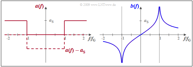
$\text{Example 5:}$ A low-pass filter has the frequency response $H(f) = 1$ ⇒ $a(f) =0 \ {\rm Np}$ in the pass band – thus for $\vert f \vert < f_{\rm G}$ – while for higher frequencies the attenuation function $a(f)$ has the constant value $a_{\rm S}$ (in Neper).
In this stop band, $H(f) = {\rm e}^{–a_{\rm S} }$ is very small but not zero.
- If the low-pass filter is to be causal and thus realizable, then the phase function $b(f)$ must be equal to the Hilbert transform of the attenuation $a(f)$ .
- Since the Hilbert transform of a constant is equal to zero, the function $a(f) - a_{\rm S}$ can be assumed in the same way.
Diese in der Grafik gestrichelt eingezeichnete Funktion ist zwischen $±f_{\rm G}$ (negativ) rechteckförmig. Entsprechend der Tabelle auf der letzten Seite gilt deshalb:
- $$b(f) = {a_{\rm S} }/{\pi} \cdot {\rm ln}\hspace{0.1cm}\left\vert \frac{f+f_{\rm G} }{f-f_{\rm G} }\right \vert \hspace{0.05cm}.$$
Jeder andere Phasenverlauf würde dagegen zu einer akausalen Impulsantwort führen.
Exercises for the chapter
Exercise 3.1: Kausalitätsbetrachtungen
Exercise 3.1Z: Hilbert-Transformierte
List of sources
- ↑ Marko, H.: Methoden der Systemtheorie. 3. Auflage. Berlin – Heidelberg: Springer, 1994.


