Contents
Considered system model
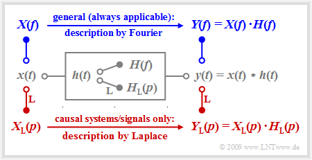
We consider a linear time-invariant system with the impulse response $h(t)$, to whose input the signal $x(t)$ is applied. The output signal $y(t)$ is then obtained as the convolution product $x(t) ∗ h(t)$.
For non-causal systems and signals, the first Fourier integral must always be applied to describe the spectral behavior, and the following is valid for the output spectrum:
- $$Y(f) = X(f) \cdot H(f) \hspace{0.05cm}.$$
The Fourier integral also continues to be valid for causal systems and signals, i.e. under the assumption
- $$x(t) = 0 \hspace{0.2cm}{\rm{f\ddot{u}r}} \hspace{0.2cm} t<0\hspace{0.05cm},\hspace{0.2cm} h(t) = 0 \hspace{0.2cm}{\rm{for}} \hspace{0.2cm} t<0 \hspace{0.3cm}\Rightarrow \hspace{0.3cm} y(t) = 0 \hspace{0.2cm}{\rm{for}} \hspace{0.2cm} t<0 \hspace{0.05cm}.$$
In this case, however, there are significant advantages in applying the Laplace transformation while taking into account certain restrictions:
- The systems treated in this way are always realizable by a circuit. The developer is not tempted to offer unrealistic solutions.
- The Laplace transform $X_{\rm L}(p)$ is always a real function of the spectral variable $p$. The fact that this variable is derived from the multiplication of the physical angular frequency $ω = 2πf$ by the imaginary unit $\rm j$ according to $p = {\rm j} · 2πf$ does not matter for the user.
- The implicit condition $x(t) = 0$ for $t < 0$ specifically allows for simpler analysis of transient behavior after switching-on processes than with the Fourier integral.
Definition of the Laplace transformation
Starting from the first Fourier integral
- $$X(f) = \int_{-\infty}^{+\infty} { x(t) \hspace{0.05cm}\cdot \hspace{0.05cm} {\rm e}^{-{\rm j}\hspace{0.05cm} 2\pi f t}}\hspace{0.1cm}{\rm d}t,$$
the Laplace transformation is obtained directly using the formal substitution $p = {\rm j} · 2πf$ for a causal time function
- $$x(t) = 0 \ \ \text{for} \ \ t < 0.$$
$\text{Definition:}$ The Laplace transform of a causal time function $x(t)$ is:
- $$X_{\rm L}(p) = \int_{0}^{\infty} { x(t) \hspace{0.05cm}\cdot \hspace{0.05cm} {\rm e}^{-p t} }\hspace{0.1cm}{\rm d}t\hspace{0.05cm}, \hspace{0.3cm}{\rm briefly}\hspace{0.3cm} X_{\rm L}(p) \quad \bullet\!\!-\!\!\!-^{\hspace{-0.25cm}\rm L}\!\!\!-\!\!\circ\quad x(t)\hspace{0.05cm}.$$
The relationship between the Laplace transform $X_{\rm L}(p)$ and the physical spectrum $X(f)$ is often given as follows:
- $$X(f) = X_{\rm L}(p) \Bigg |_{{\hspace{0.1cm} p\hspace{0.05cm}={\rm \hspace{0.05cm} j\hspace{0.05cm}2\pi \it f}}}.$$
- However, if the signal $x(t)$ has periodic components and thus the spectral function $X(f)$ contains Dirac functions, then this equation is not applicable.
- In this case, $p = α + {\rm j} · 2πf$ must be applied and then the limit $α → 0$ must be formed.
$\text{Example 1:}$ We assume the unilaterally and exponentially decreasing time function corresponding to the sketch in $\text{Example 1}$ of the chapter "Conclusions from the Allocation Theorem":
- $$x(t) = \left\{ \begin{array}{c} 0 \\ 0.5 \\ {\rm e}^{-t/T} \end{array} \right.\quad \quad \begin{array}{c} {\rm{for} } \\ {\rm{for} } \\ {\rm{for} } \end{array}\begin{array}{*{20}c}{ t < 0\hspace{0.05cm},} \\ { t = 0\hspace{0.05cm},} \\{ t > 0\hspace{0.05cm}.} \end{array}$$
Thus, the Laplace transform is:
- $$X_{\rm L}(p) = \int_{0}^{\infty} {\rm e}^{-t/T} \cdot {\rm e}^{-pt} \hspace{0.1cm}{\rm d}t= \frac {1}{p + 1/T} \cdot {{\rm e}^{-(p+1/T) \hspace{0.08cm}\cdot \hspace{0.08cm}t}}\hspace{0.15cm}\Bigg \vert_{t \hspace{0.05cm}=\hspace{0.05cm} 0}^{\infty}= \frac {1}{p + 1/T} \hspace{0.05cm} .$$
Considering $p = {\rm j} · 2πf$, the conventional spectral function with respect to $f$ is obtained:
- $$X(f) = \frac {1}{{\rm j \cdot 2\pi \it f} + 1/T} = \frac {T}{1+{\rm j \cdot 2\pi \it fT}} \hspace{0.05cm} .$$
In contrast, if we consider the frequency response of a low-pass filter of first-order whose impulse response $h(t)$ differs from the above time function by the factor $1/T$ , then the following holds for the Laplace transform and the Fourier transform, respectively:
- $$H_{\rm L}(p)= \frac {1/T}{p + 1/T}= \frac {1}{1 + p \cdot T} \hspace{0.05cm} , \hspace{0.8cm}H(f) = \frac {1}{1+{\rm j \cdot 2\pi \it fT} } = \frac {1}{1+{\rm j} \cdot f/f_{\rm G} } \hspace{0.05cm} .$$
Often, as in this equation, the 3dB cut-off frequency $f_{\rm G} = 1/(2πT)$ is used instead of the parameter $T$ .
Some important Laplace correspondences
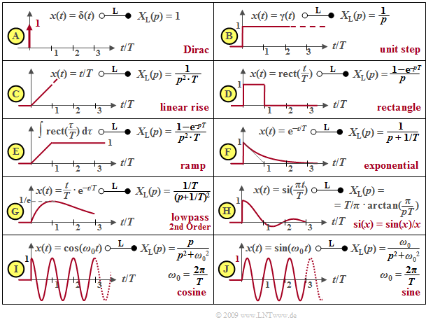
Some important Laplace correspondences are compiled subsequently. All time signals $x(t)$ considered here are assumed to be dimensionless. For this reason, $X_{\rm L}(p)$ then always has the unit "second" as an integral over time.
- The Laplace transform of the Dirac function $δ(t)$ is $X_{\rm L}(p) = 1$ $($diagram $\rm A)$. $X_{\rm L}(p) = 1/p$ is obtained for the step function $γ(t)$ $($diagram $\rm B)$ by applying the integration theorem and from this by multiplication by $1/(pT)$ the Laplace transform of the linearly increasing function $x(t) = t/T$ for $t > 0$ is obtained $($diagram $\rm C)$.
- The rectangular function can be generated from the subtraction of two step functions $γ(t)$ and $γ(t – T)$ separated by $T$ so that the Laplace transform $X_{\rm L}(p) = (1 – {\rm e}^{–pT})/p$ is obtained according to the shifting theorem $($diagram $\rm D)$. By integration the ramp function or after multiplication by $1/(pT)$ its Laplace transform is obtained from it $($diagram $\rm E)$.
- The exponential function $($diagram $\rm F)$ has already been considered on the last page . Considering the factor $1/T$, this is at the same time the impulse response of a low-pass filter of first-order. The $p$–spectral function of a low-pass filter of second-order with the time function $x(t) = t/T · {\rm e}^{–t/T}$ (diagram $\rm G$) is obtained by squaring.
- In addition to the causal $\rm si$–function $($diagram $\rm H)$, the Laplace transforms of the causal cosine and sine functions $($diagrams $\rm I$ and $\rm J)$, which result in $p/(p^2 + ω_0^2)$ and $ω_0/(p^2 + ω_0^2)$ respectively, are also given in the table. Here, $ω_0 = 2πf_0 = 2π/T$ denotes the so-called angular frequency.
Pole-zero representation of circuits
Any linear time-invariant system (LTI) which can be realized by a circuit of discrete time-constant components such as
- resistances $(R)$,
- capacitances $(C)$,
- inductances $(L)$ and
- amplifier elements,
has a fractional-rational $p$–transfer function:
- $$H_{\rm L}(p)= \frac {A_Z \cdot p^Z +\text{...} + A_2 \cdot p^2 + A_1 \cdot p + A_0} {B_N \cdot p^N +\text{...} \ + B_2 \cdot p^2 + B_1 \cdot p + B_0}= \frac {Z(p)}{N(p)} \hspace{0.05cm} .$$
All coefficients of the numerator ⇒ $A_Z, \text{...} \ , A_0$ and of the denominator ⇒ $B_N, \text{...} , B_0$ are real. Furthermore,
- $Z$ denotes the degree of the numerator polynomial $Z(p)$,
- $N$ denotes the degree of the denominator polynomial $N(p)$.
$\text{Equivalent pole-zero representation:}$ The following can be formulated for the $p$–transfer function, too:
- $$H_{\rm L}(p)= K \cdot \frac {\prod\limits_{i=1}^Z p - p_{\rm o i} } {\prod\limits_{i=1}^N p - p_{\rm x i} }= K \cdot \frac {(p - p_{\rm o 1})(p - p_{\rm o 2})\cdot \text{...} \ \cdot (p - p_{ {\rm o} \hspace{-0.03cm} Z})} {(p - p_{\rm x 1})(p - p_{\rm x 2})\cdot \text{...} \cdot (p - p_{ {\rm x} \hspace{-0.03cm} N})} \hspace{0.05cm} .$$
The $Z + N + 1$ parameters signify:
- $K = A_Z/B_N$ is a constant factor. If $Z = N$ holds, then this is dimensionless.
- The solutions of the equation $Z(p) = 0$ result in the $Z$ zeros $p_{\rm o1},\text{...} \ , p_{\rm oZ}$ of $H_{\rm L}(p)$.
- The zeros of the denominator polynomial $N(p)$ yield the $N$ pole locations (or poles for short).
The transformation is unique. This can be seen from the fact that the $p$–transfer function is also determined only by $Z + N + 1$ free parameters according to the first equation since one of the coefficients $A_Z, \text{...} \ , A_0, B_N, \text{...} \ , B_0$ can be normalized to $1$ without changing the quotient.
$\text{Example 2:}$ We consider the drawn two-port network with an inductance $L$ $($complex resistance $pL)$ in the longitudinal branch as well as the series connection of an ohmic resistance $R$ and a capacitance $C$ with the complex resistance $1/(pC)$ in the transverse branch.
Thus, the $p$–transfer function is:
- $$H_{\rm L}(p)= \frac {Y_{\rm L}(p)} {X_{\rm L}(p)}= \frac {R + {1}/{(pC)} } {pL + R +{1}/{(pC)} }= \frac {1 + p \cdot{RC} } {1 + p \cdot{RC}+ p^2 \cdot{LC} } \hspace{0.05cm} .$$
If $p = {\rm j} · 2πf$ is set, then the Fourier transfer function (or the frequency response) is obtained. If the numerator and denominator in the above equation are divided by $LC$, then the following is obtained:
- $$H_{\rm L}(p)= \frac {R} {L}\cdot \frac {p + {1}/{(RC)} } {p^2 + {R}/ {L}\cdot p + {1}/{(LC)} }= K \cdot \frac {p - p_{\rm o } } {(p - p_{\rm x 1})(p - p_{\rm x 2})} \hspace{0.05cm} .$$
In the right-hand side of the equation, the transfer function $H_{\rm L}(p)$ is given in pole-zero notation. By comparison of coefficients the following values are obtained for $R = 50 \ \rm Ω$, $L = 25\ \rm µ H$ and $C = 62.5 \ \rm nF$ :
- the constant $K = R/L = 2 · 10^6 \cdot 1/{\rm s}$,
- the zero $p_{\rm o} = -1/(RC) = -0.32 · 10^6 \cdot 1/{\rm s},$
- the two poles $p_{\rm x1}$ and $p_{\rm x2}$ as the solution of the equation
- $$p^2 + \frac {R} {L}\cdot p + \frac{1}{LC} = 0 \hspace{0.3cm}\Rightarrow \hspace{0.3cm} p_{\rm x 1,\hspace{0.05cm}2 }= -\frac {R} {2L}\pm \sqrt{\frac {R^2} {4L^2}- \frac{1}{LC} }$$
- $$\Rightarrow \hspace{0.3cm} p_{\rm x 1,\hspace{0.05cm}2 }= -10^6 \cdot {1}/{\rm s} \pm \sqrt{10^{12} \cdot {1} /{\rm s^2}-0.64 \cdot 10^{12} \cdot {1}/ {\rm s^2} }\hspace{0.3cm} \Rightarrow \hspace{0.3cm} p_{\rm x 1 }= -0.4 \cdot 10^6\cdot {1}/ {\rm s},\hspace{0.2cm}p_{\rm x 2 }= -1.6 \cdot 10^6\cdot {1}/ {\rm s} \hspace{0.05cm} .$$
In the above graph, the pole-zero diagram is given on the right-hand side.
- The two axes denote the real and imaginary parts of the variable $p$, each normalized to the value $10^6 · \rm 1/s\; (= 1/µs)$.
- The zero at $p_{\rm o} =\, –0.32$ can be seen as a circle and the poles at $p_{\rm x1} = \,–0.4$ and $p_{\rm x2} = \,–1.6$ as crosses.
Properties of poles and zeros
The transfer function $H_{\rm L}(p)$ of any realizable circuit is fully described by $Z$ zeros and $N$ poles together with a constant $K$ where the following restrictions apply:
- The following always holds: $Z ≤ N$. The $p$–transfer function would also be "infinitely large" with $Z > N$ in the limiting case for $p → ∞$ (i.e. for very high frequencies).
- The zeros $p_{\rm oi}$ and the poles $p_{ {\rm x}i}$ are generally complex, and have the unit $\rm 1/s$ like $p$ . If $Z < N$ holds, then the constant $K$ also has a unit.
- The poles and zeros can be real as shown in the last example. If they are complex, then two poles and two zeros always occur as complex conjugates, respectively, since $H_{\rm L}(p)$ always represents a real fractional-rational function.
- All poles lie in the left half-plane or on the imaginary axis (limiting case). This property follows from the required and assumed causality together with the fundamental theorem of the theory of functions, which will be stated in the next chapter.
- Zeros can occur in both the left and right $p$–half planes or also on the imaginary axis. An example of zeros in the right half plane can be found in Exercise 3.4Z, which deals with all-pass filters.
- In the so-called minimum-phase systems, not only poles are forbidden in the right $p$–half plane but also zeros. The real part of all singularities here is never positive.
These properties are now illustrated by three examples.
$\text{Example 3:}$ Starting from the [[Linear_and_Time_Invariant_Systems/Laplace_Transform_and_p-Transfer_Function#Pole-zero_representation_of_circuits |Vierpolschaltung]] $(L$ im Längszweig, $R$ and $C$ im Querzweig$)$ können die charakteristischen Größen der Übertragungsfunktion wie folgt angegeben werden:
- $$K = 2A, \hspace{0.2cm}p_{\rm x 1,\hspace{0.05cm}2 }= -A \pm \sqrt{A^2-B^2}, \hspace{0.2cm}p_{\rm o }= - \frac{B^2}{2A} \hspace{0.05cm} \hspace{0.2cm} {\rm mit } \hspace{0.2cm} A = \frac {R} {2L}, \hspace{0.2cm}B = \frac{1}{\sqrt{LC} } \hspace{0.05cm}.$$
Die Grafik zeigt drei verschiedene Diagramme mit unterschiedlichen Kapazitätswerten $C$. Es gilt stets $R = 50 \ \rm Ω$ und $L = 25 \ \rm µ H$. Die Achsen sind auf die Variable $A = R/(2L) = 10^6 · \rm 1/s$ normiert, und der konstante Faktor ist jeweils $K = 2A = 2 · 10^6 · \rm 1/s.$
- Für $B < A$ erhält man zwei reelle Pole und eine Nullstelle rechts von $-A/2$. Für $C = 62.5 \ \rm nF$ ergibt sich (linkes Diagramm):
- $$ {B}/ {A}= 0.8 \hspace{0.3cm}\Rightarrow \hspace{0.3cm} p_{\rm x 1}/A = -0.4 , \hspace{0.2cm}p_{\rm x 2}/A= -1.6 , \hspace{0.2cm}p_{\rm o}/A= -0.32 \hspace{0.05cm} .$$
- Für $B > A$ ergeben sich zwei konjugiert–komplexe Pole und eine Nullstelle links von $-A/2$. Für $C = 8 \ \rm nF$ (rechtes Diagramm):
- $${B}/ {A}= \sqrt{5} \hspace{0.3cm}\Rightarrow \hspace{0.3cm} p_{\rm x 1,\hspace{0.05cm}2 }/A= -1\pm {\rm j}\cdot 2,\hspace{0.2cm}p_{\rm o}/A\approx -2.5 \hspace{0.05cm} .$$
- Der Fall $A = B$ führt zu einer reellen doppelten Polstelle und einer Nullstelle bei $– A/2$. Für $C = 400 \ \rm nF$ (mittleres Diagramm):
- $$ {B}/ {A}= 1 \hspace{0.3cm}\Rightarrow \hspace{0.3cm} p_{\rm x 1}/A= p_{\rm x 2}/A= -1, \hspace{0.2cm}p_{\rm o}/A= -0.5 \hspace{0.05cm} .$$
The impulse responses $h(t)$ ergeben sich entsprechend dem folgenden Kapitel Laplace–Rücktransformation wie folgt:
- Bei der linken Konstellation ist $h(t)$ aperiodisch abklingend.
- Bei der rechten Konstellation ist $h(t)$ gedämpft oszillierend.
- Bei der mittleren Konstellation spricht man vom aperiodischen Grenzfall.
Grafische Ermittlung von Dämpfung und Phase
Gegeben sei die $p$–Übertragungsfunktion in der Pol–Nullstellen–Notation:
- $$H_{\rm L}(p)= K \cdot \frac {\prod\limits_{i=1}^Z (p - p_{\rm o i})} {\prod\limits_{i=1}^N (p - p_{\rm x i})}= K \cdot \frac {(p - p_{\rm o 1})(p - p_{\rm o 2})\cdot \text{...} \cdot (p - p_{ {\rm o} \hspace{-0.03cm} Z})} {(p - p_{\rm x 1})(p - p_{\rm x 2})\cdot \text{...} \cdot (p - p_{ {\rm x} \hspace{-0.03cm} N})} \hspace{0.05cm} .$$
Zum herkömmlichen Frequenzgang $H(f)$ kommt man, indem man das Argument $p$ von $H_{\rm L}(p)$ durch ${\rm j} \cdot 2πf$ ersetzt:
- $$H(f)= K \cdot \frac {({\rm j} \cdot 2\pi \hspace{-0.05cm}f - p_{\rm o 1})({\rm j} \cdot 2\pi \hspace{-0.05cm}f - p_{\rm o 2})\cdot \text{...} \cdot ({\rm j} \cdot 2\pi \hspace{-0.05cm}f - p_{ {\rm o} \hspace{-0.03cm} Z})} {({\rm j} \cdot 2\pi \hspace{-0.05cm}f - p_{\rm x 1})({\rm j} \cdot 2\pi \hspace{-0.05cm}f - p_{\rm x 2})\cdot \text{...}\cdot ({\rm j} \cdot 2\pi \hspace{-0.05cm}f - p_{ {\rm x} \hspace{-0.03cm} N})} \hspace{0.05cm} .$$
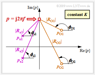
Wir betrachten nun eine feste Frequenz $f$ und beschreiben die Abstände und Winkel aller Nullstellen durch Vektoren:
- $$R_{ {\rm o} i} = {\rm j} \cdot 2\pi \hspace{-0.05cm}f - p_{ {\rm o} i}= |R_{{\rm o} i}| \cdot {\rm e}^{\hspace{0.03cm}{\rm j}\hspace{0.03cm}\cdot\hspace{0.03cm}\phi_{ {\rm o} i} }, \hspace{0.3cm}i= 1, \text{...}\ , Z \hspace{0.05cm} .$$
In gleicher Weise gehen wir für die Polstellen vor:
- $$R_{ {\rm x} i} = {\rm j} \cdot 2\pi \hspace{-0.05cm}f - p_{ {\rm x} i}= |R_{ {\rm x} i}| \cdot {\rm e}^{\hspace{0.03cm}{\rm j}\hspace{0.03cm}\cdot\hspace{0.03cm}\phi_{ {\rm x} i} }, \hspace{0.3cm}i= 1, \text{...}\ , N \hspace{0.05cm} .$$
Die Grafik zeigt die Beträge und Phasenwinkel für ein System
- mit $Z = 2$ Nullstellen in der rechten Halbebene
- und $N = 2$ Polstellen in der linken Halbebene.
Zu berücksichtigen ist zudem die Konstante $K$.
Mit dieser Vektordarstellung kann für den Frequenzgang geschrieben werden:
- $$H(f)= K \cdot \frac {|R_{ {\rm o} 1}| \cdot |R_{ {\rm o} 2}|\cdot ... \cdot |R_{ {\rm o} \hspace{-0.03cm} Z}|} {|R_{ {\rm x} 1}| \cdot |R_{ {\rm x} 2}|\cdot \text{...} \cdot |R_{ {\rm x} \hspace{-0.03cm} N}|} \cdot {\rm e^{\hspace{0.03cm}{\rm j} \hspace{0.05cm}\cdot [ \phi_{ {\rm o} 1}\hspace{0.1cm}+ \hspace{0.1cm}\phi_{ {\rm o} 2} \hspace{0.1cm}+ \hspace{0.1cm}\hspace{0.1cm}\text{...}. \hspace{0.1cm} + \hspace{0.1cm}\phi_{ {\rm o} \hspace{-0.03cm}{\it Z}}\hspace{0.1cm}- \hspace{0.1cm}\phi_{ {\rm x} 1}\hspace{0.1cm}- \hspace{0.1cm}\phi_{ {\rm x} 2} \hspace{0.1cm}- \hspace{0.1cm}... \hspace{0.1cm} - \hspace{0.1cm} \phi_{ {\rm x} \hspace{-0.03cm}{\it N} }]} } \hspace{0.05cm} .$$
Stellt man $H(f)$ durch die Dämpfungsfunktion $a(f)$ und die Phasenfunktion $b(f)$ nach der allgemein gültigen Beziehung $H(f) = {\rm e}^{-a(f)\hspace{0.05cm}- \hspace{0.05cm}{\rm j} \hspace{0.05cm}\cdot \hspace{0.05cm}b(f)}$ dar, so erhält man durch den Vergleich mit der obigen Gleichung das folgende Ergebnis:
- Bei geeigneter Normierung aller dimensionsbehafteten Größen gilt für die Dämpfung in Neper $(1 \ \rm Np$ entspricht $8.686 \ \rm dB)$:
- $$a(f) = -{\rm ln} \hspace{0.1cm} K + \sum \limits_{i=1}^N {\rm ln} \hspace{0.1cm} |R_{ {\rm x} i}|- \sum \limits_{i=1}^Z {\rm ln} \hspace{0.1cm} |R_{ {\rm o} i}| \hspace{0.05cm} .$$
- Die Phasenfunktion in Radian $\rm (rad)$ ergibt sich entsprechend der oberen Skizze zu
- $$b(f) = \phi_K + \sum \limits_{i=1}^N \phi_{ {\rm x} i}- \sum \limits_{i=1}^Z \phi_{ {\rm o} i}\hspace{0.2cm}{\rm mit} \hspace{0.2cm} \phi_K = \left\{ \begin{array}{c} 0 \\ \pi \end{array} \right. \begin{array}{c} {\rm{f\ddot{u}r} } \\ {\rm{f\ddot{u}r} } \end{array}\begin{array}{*{20}c} { K > 0\hspace{0.05cm},} \\ { K <0\hspace{0.05cm}.} \end{array}$$
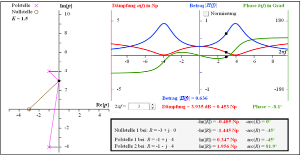
$\text{Example 4:}$ Die Grafik verdeutlicht die Berechnung
- der Dämpfungsfunktion $a(f)$ ⇒ roter Kurvenverlauf, und
- der Phasenfunktion $b(f)$ ⇒ grüner Kurvenverlauf
eines Vierpols, der durch den Faktor $K = 1.5$, eine Nullstelle bei $-3$ und zwei Pole bei $–1 \pm {\rm j} · 4$ festliegt.
Die angegebenen Zahlenwerte gelten für die Frequenz $2πf = 3$:
- $$a \big [f = {3}/({2\pi}) \big ] = 0.453\,\,{\rm Np}= 3.953\,\,{\rm dB}$$
- $$\Rightarrow \hspace{0.4cm}\big \vert H \big [f = {3}/({2\pi}) \big ]\big \vert = 0.636,$$
- $$ b\big [f = {3}/({2\pi}) \big ] = -8.1^\circ \hspace{0.05cm} .$$
Die Herleitung dieser Zahlenwerte ist im umrahmten Block verdeutlicht.
Für den Betragsfrequenzgang $\vert H(f)\vert$ ⇒ blauer Kurvenverlauf ergibt sich ein bandpassähnlicher Verlauf mit
- $$\vert H(f = 0)\vert \approx 0.25\hspace{0.05cm}, \hspace{0.5cm} \vert H(f = {4}/(2\pi)\vert \approx 0637\hspace{0.05cm},\hspace{0.5cm} \vert H(f \rightarrow \infty)\vert= 0 \hspace{0.05cm} .$$
Exercises for the chapter
Exercise 3.2: Laplace Transform
Exercise 3.2Z: Laplace and Fourier
Exercise 3.3: p-Transfer Function
Exercise 3.3Z: High- and Low-Pass Filters in p-Form
Exercise 3.4: Attenuation and Phase Response
Exercise 3.4Z: Various All-Pass Filters


