Contents
# OVERVIEW OF THE FOURTH MAIN CHAPTER #
The fourth main chapter provides an abstract description of digital signal transmission, which is based on basis functions and signal space constellations. This makes it possible to treat very different configurations - for example band-pass systems and those for the baseband - in a uniform way. The optimal receiver in each case has the same structure in all cases.
The following are dealt with in detail:
- the meaning of basis functions and finding them using the Gram-Schmidt method,
- the structure of the optimal receiver for baseband transmission,
- the theorem of irrelevance and its importance for the derivation of optimal detectors,
- the optimal receiver for the AWGN channel and implementation aspects,
- the system description by complex or $N$–dimensional Gaussian noise,
- the error probability calculation and approximation under otherwise ideal conditions,
- the application of the signal space description to carrier frequency systems,
- the different results for OOK, M-ASK, M-PSK, M-QAM and M-FSK,
- the different results for coherent and non-coherent demodulation.
Almost all results of this chapter have already been derived in previous sections. However, the approach is fundamentally new:
- In the $\rm LNTwww$ book "Modulation Methods" and in the first three chapters of this book, the specific system properties were already taken into account in the derivations – for example, whether the digital signal is transmitted in baseband or whether digital amplitude, frequency or phase modulation is present.
- Here the systems are to be abstracted in such a way that they can be treated uniformly. The optimal receiver in each case has the same structure in all cases, and the error probability can also be specified for non-Gaussian distributed noise.
It should be noted that this rather global approach means that certain system deficiencies can only be recorded very imprecisely, such as
- the influence of a non-optimal receiver filter on the error probability,
- an incorrect threshold (threshold drift), or
- phase jitter (fluctuations in sampling times).
In particular in the presence of intersymbol interference, the procedure should therefore continue in accordance with the third main chapter.
The description is based on the script [KöZ08][1] by Ralf Kötter and Georg Zeitler, which is closely based on the textbook [WJ65][2]. Gerhard Kramer, who has held the chair at the LNT since 2010, treats the same topic with very similar nomenclature in his lecture [Kra17][3].
In order not to make reading unnecessarily difficult for our own students at the TU Munich, we stick to this nomenclature as far as possible, even if it deviates from other $\rm LNTwww$ chapters.
Nomenclature in the fourth chapter
Compared to the other chapters in $\rm LNTwww$, the following nomenclature differences arise here:
- The "message" to be transmitted is an integer value $m \in \{m_i\}$ with $i = 0$, ... , $M-1$, where $M$ specifies the symbol set size. If it simplifies the description, $i = 1$, ... , $M$ is induced.
- The result of the decision process at the receiver is also an integer with the same symbol alphabet as at the transmitter. This result is also referred to as the estimated value:
- $$\hat{m} \in \{m_i \}, \hspace{0.2cm} i = 0, 1, \text{...}\hspace{0.05cm} , M-1\hspace{0.2cm} ({\rm or}\,\,i = 1, 2, \text{...}\hspace{0.05cm}, M) \hspace{0.05cm}.$$
- The "symbol error probability" $\rm Pr(symbol error)$ or $p_{\rm S}$ is usually referred to as follows in this main chapter:
- $${\rm Pr} ({\cal E}) = {\rm Pr} ( \hat{m} \ne m) = 1 - {\rm Pr} ({\cal C}), \hspace{0.4cm}\text{complementary event:}\hspace{0.2cm} {\rm Pr} ({\cal C}) = {\rm Pr} ( \hat{m} = m) \hspace{0.05cm}.$$
- In a "probability density function" (PDF), a distinction is now made between the random variable ⇒ $r$ and the realization ⇒ $\rho$ according to $p_r(\rho)$. $f_r(r)$ was used for a PDF.
- With the notation $p_r(\rho)$, $r$ and $\rho$ Sare scalars. On the other hand, if random variable and realization are vectors (of suitable length), this is expressed in bold type: $p_{ \boldsymbol{ r}}(\boldsymbol{\rho})$ with the vectors $ \boldsymbol{ r}$ and $\boldsymbol{\rho}$.
- In order to avoid confusion with energy values, the threshold value is now called $G$ instead of $E$ and this is mainly referred to as the decision limit in this chapter.
- Based on the two real and energy-limited time functions $x(t)$ and $y(t)$, the "inner product" is:
- $$<\hspace{-0.1cm}x(t), \hspace{0.05cm}y(t) \hspace{-0.1cm}> \hspace{0.15cm}= \int_{-\infty}^{+\infty}x(t) \cdot y(t)\,d \it t \hspace{0.05cm}.$$
- This results in the "Euklidian norm" or "2–norm" (or "norm" for short):
- $$||x(t) || = \sqrt{<\hspace{-0.1cm}x(t), \hspace{0.05cm}x(t) \hspace{-0.1cm}>} \hspace{0.05cm}.$$
Compared to the script $\rm [KöZ08]$[1], the naming differs as follows:
- The probability of the event $E$ is here ${\rm Pr}(E)$ instead of $P(E)$. This nomenclature change was also made because in some equations probabilities and powers appear together.
- Band–pass signals are still marked with the index "BP" and not with a tilde as in [KöZ08][1]. The corresponding low-pass signal is (usually) provided with the index "TP".
Orthonormal basis functions
In this chapter, we assume a set $\{s_i(t)\}$ of possible transmitted signals that are uniquely assigned to the possible messages $m_i$. With $i = 1$, ... , $M$ holds:
- $$m \in \{m_i \}, \hspace{0.2cm} s(t) \in \{s_i(t) \}\hspace{-0.1cm}: \hspace{0.3cm} m = m_i \hspace{0.1cm} \Leftrightarrow \hspace{0.1cm} s(t) = s_i(t) \hspace{0.05cm}.$$
For what follows, we further assume that the $M$ signals $s_i(t)$ are "energy-limited", which usually means at the same time that they are of finite duration only.
$\text{Theorem:}$ Any set $\{s_1(t), \hspace{0.05cm} \text{...} \hspace{0.05cm} , s_M(t)\}$ of energy-limited signals can be evolved into $N \le M$ orthonormal basis functions $\varphi_1(t), \hspace{0.05cm} \text{...} \hspace{0.05cm} , \varphi_N(t)$. It holds:
- $$s_i(t) = \sum\limits_{j = 1}^{N}s_{ij} \cdot \varphi_j(t) , \hspace{0.3cm}i = 1,\hspace{0.05cm} \text{...}\hspace{0.1cm} , M, \hspace{0.3cm}j = 1,\hspace{0.05cm} \text{...} \hspace{0.1cm}, N \hspace{0.05cm}.$$
In each case, two basis functions $\varphi_j(t)$ and $\varphi_k(t)$ must be orthonormal to each other, that is, it must hold $(\delta_{jk}$ is called the "Kronecker symbol" or the "Kronecker delta"$)$:
- $$<\hspace{-0.1cm}\varphi_j(t), \hspace{0.05cm}\varphi_k(t) \hspace{-0.1cm}> = \int_{-\infty}^{+\infty}\varphi_j(t) \cdot \varphi_k(t)\,d \it t = {\rm \delta}_{jk} = \left\{ \begin{array}{c} 1 \\ 0 \end{array} \right.\quad \begin{array}{*{1}c} {\rm if}\hspace{0.1cm}j = k \\ {\rm if}\hspace{0.1cm} j \ne k \\ \end{array} \hspace{0.05cm}.$$
Here, the parameter $N$ indicates how many basis functions $\varphi_j(t)$ are needed to represent the $M$ possible transmitted signals. In other words: $N$ is the dimension of the vector space spanned by the $M$ signals. Here, the following holds:
- If $N = M$, all transmitted signals are orthogonal to each other. They are not necessarily orthonormal, i.e. the energies $E_i = <\hspace{-0.1cm}s_i(t), \hspace{0.05cm}s_i(t) \hspace{-0.1cm}>$ may well be unequal to one.
- The case $N < M$ arises when at least one signal $s_i(t)$ can be represented as a linear combination of basis functions $\varphi_j(t)$ that have resulted from other signals $s_j(t) \ne s_i(t)$.
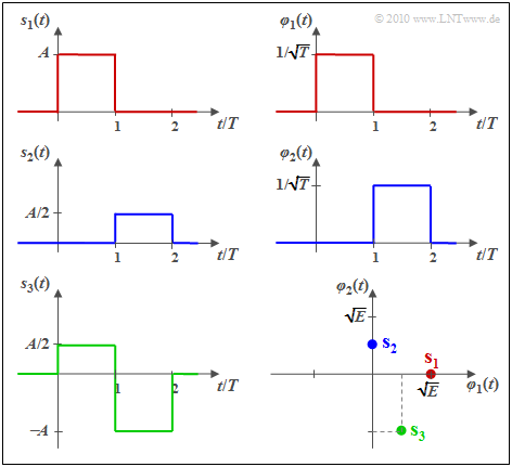
$\text{Example 1:}$ We consider $M = 3$ energy-limited signals according to the graph. One recognizes immediately:
- The signals $s_1(t)$ and $s_2(t)$ are orthogonal to each other.
- The energies are $E_1 = A^2 \cdot T = E$ and $E_2 = (A/2)^2 \cdot T = E/4$.
- The basis functions $\varphi_1(t)$ and $\varphi_2(t)$ are equal in form to $s_1(t)$ and $s_2(t)$, respectively, and both have energy one:
- $$\varphi_1(t)=\frac{s_1(t)}{\sqrt{E_1} } = \frac{s_1(t)}{\sqrt{A^2 \cdot T} } = \frac{1}{\sqrt{ T} } \cdot \frac{s_1(t)}{A}$$
- $$\hspace{0.5cm}\Rightarrow \hspace{0.1cm}s_1(t) = s_{11} \cdot \varphi_1(t)\hspace{0.05cm},\hspace{0.1cm}s_{11} = \sqrt{E}\hspace{0.05cm},$$
- $$\varphi_2(t) =\frac{s_2(t)}{\sqrt{E_2} } = \frac{s_2(t)}{\sqrt{(A/2)^2 \cdot T} } = \frac{1}{\sqrt{ T} } \cdot \frac{s_2(t)}{A/2}\hspace{0.05cm}$$
- $$\hspace{0.5cm}\Rightarrow \hspace{0.1cm}s_2(t) = s_{21} \cdot \varphi_2(t)\hspace{0.05cm},\hspace{0.1cm}s_{21} = {\sqrt{E} }/{2}\hspace{0.05cm}.$$
- The signal $s_3(t)$ can be expressed by the previously determined basis functions $\varphi_1(t)$ and $\varphi_2(t)$:
- $$s_3(t) =s_{31} \cdot \varphi_1(t) + s_{32} \cdot \varphi_2(t)\hspace{0.05cm},$$
- $$\hspace{0.5cm}\Rightarrow \hspace{0.1cm} s_{31} = {A}/{2} \cdot \sqrt {T}= {\sqrt{E} }/{2}\hspace{0.05cm}, \hspace{0.2cm}s_{32} = - A \cdot \sqrt {T} = -\sqrt{E} \hspace{0.05cm}.$$
In the lower right image, the signals are shown in a 2D representation with the basis functions $\varphi_1(t)$ and $\varphi_2(t)$ as axes, where $E = A^2 \cdot T$ and the relation to the other graphs can be seen by the coloring.
The vectorial representatives of the signals $s_1(t)$, $s_2(t)$ and $s_3(t)$ in this two-dimensional vector space can be read from this as follows:
- $$\mathbf{s}_1 = (\sqrt{ E}, \hspace{0.1cm}0), $$
- $$\mathbf{s}_2 = (0, \hspace{0.1cm}\sqrt{ E}/2), $$
- $$\mathbf{s}_3 = (\sqrt{ E}/2,\hspace{0.1cm}-\sqrt{ E} ) \hspace{0.05cm}.$$
The Gram-Schmidt method
In $\text{example 1}$ in the last section, the specification of the two orthonormal basis functions $\varphi_1(t)$ and $\varphi_2(t)$ was very easy, because they were of the same form as $s_1(t)$ and $s_2(t)$, respectively. The "Gram-Schmidt method" finds the basis functions $\varphi_1(t)$, ... , $\varphi_N(t)$ for arbitrary predefinable signals $s_1(t)$, ... , $s_M(t)$, as follows:
- Die erste Basisfunktion $\varphi_1(t)$ ist stets formgleich mit $s_1(t)$. Es gilt:
- $$\varphi_1(t) = \frac{s_1(t)}{\sqrt{E_1}} = \frac{s_1(t)}{|| s_1(t)||} \hspace{0.3cm}\Rightarrow \hspace{0.3cm} || \varphi_1(t) || = 1, \hspace{0.2cm}s_{11} =|| s_1(t)||,\hspace{0.2cm}s_{1j} = 0 \hspace{0.2cm}{\rm f{\rm \ddot{u}r }}\hspace{0.2cm} j \ge 2 \hspace{0.05cm}.$$
- Es wird nun angenommen, dass aus den Signalen $s_1(t)$, ... , $s_{k-1}(t)$ bereits die Basisfunktionen $\varphi_1(t)$, ... , $\varphi_{n-1}(t)$ berechnet wurden $(n \le k)$. Dann berechnen wir mittels $s_k(t)$ die Hilfsfunktion
- $$\theta_k(t) = s_k(t) - \sum\limits_{j = 1}^{n-1}s_{kj} \cdot \varphi_j(t) \hspace{0.4cm}{\rm mit}\hspace{0.4cm} s_{kj} = \hspace{0.1cm} < \hspace{-0.1cm} s_k(t), \hspace{0.05cm}\varphi_j(t) \hspace{-0.1cm} >, \hspace{0.2cm} j = 1, \hspace{0.05cm} \text{...}\hspace{0.05cm}, n-1\hspace{0.05cm}.$$
- Ist $\theta_k(t) \equiv 0$ ⇒ $||\theta_k(t)|| = 0$, so liefert $s_k(t)$ keine neue Basisfunktion. Vielmehr lässt sich dann $s_k(t)$ durch die $n-1$ bereits vorher gefundenen Basisfunktionen $\varphi_1(t)$, ... , $\varphi_{n-1}(t)$ ausdrücken:
- $$s_k(t) = \sum\limits_{j = 1}^{n-1}s_{kj}\cdot \varphi_j(t) \hspace{0.05cm}.$$
- Eine neue Basisfunktion (nämlich die $n$–te) ergibt sich, falls $||\theta_k(t)|| \ne 0$ ist:
- $$\varphi_n(t) = \frac{\theta_k(t)}{|| \theta_k(t)||} \hspace{0.3cm}\Rightarrow \hspace{0.3cm} || \varphi_n(t) || = 1\hspace{0.05cm}.$$
Diese Prozedur wird fortgesetzt, bis alle $M$ Signale berücksichtigt wurden. Danach hat man alle $N \le M$ orthonormalen Basisfunktionen $\varphi_j(t)$ gefunden. Der Sonderfall $N = M$ ergibt sich nur dann, wenn alle $M$ Signale linear voneinander unabhängig sind.
Dieses Verfahren wird nun an einem Beispiel verdeutlicht. Wir verweisen auch auf das interaktive Applet Gram–Schmidt–Verfahren.
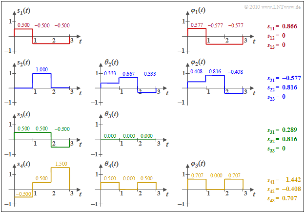
$\text{Beispiel 2:}$ Wir betrachten die $M = 4$ energiebegrenzten Signale $s_1(t)$, ... , $s_4(t)$ entsprechend der Grafik. Zur Vereinfachung der Berechnungen ist hier sowohl die Amplitude als auch die Zeit normiert.
Man erkennt aus diesen Skizzen:
- Die Basisfunktion $\varphi_1(t)$ ist formgleich mit $s_1(t)$. Wegen $E_1 = \vert \vert s_1(t) \vert \vert ^3 = 3 \cdot 0.5^2 = 0.75$ ergibt sich $s_{11} = \vert \vert s_1(t) \vert \vert = 0.866$. $\varphi_1(t)$ selbst besitzt abschnittsweise die Werte $\pm 0.5/0.866 = \pm0.577$.
- Zur Berechnung der Hilfsfunktion $\theta_2(t)$ berechnen wir
- $$s_{21} = \hspace{0.1cm} < \hspace{-0.1cm} s_2(t), \hspace{0.05cm}\varphi_1(t) \hspace{-0.1cm} > \hspace{0.1cm} = 0 \cdot (+0.577) + 1 \cdot (-0.577)+ 0 \cdot (-0.577)= -0.577$$
- $$ \Rightarrow \hspace{0.3cm}\theta_2(t) = s_2(t) - s_{21} \cdot \varphi_1(t) = (0.333, 0.667, -0.333) \hspace{0.3cm}\Rightarrow \hspace{0.3cm}\vert \vert \theta_2(t) \vert \vert^2 = (1/3)^2 + (2/3)^2 + (-1/3)^2 = 0.667$$
- $$ \Rightarrow \hspace{0.3cm} s_{22} = \sqrt{0.667} = 0.816,\hspace{0.3cm} \varphi_2(t) = \theta_2(t)/s_{22} = (0.408, 0.816, -0.408)\hspace{0.05cm}. $$
- Die inneren Produkte zwischen $s_1(t)$ mit $\varphi_1(t)$ bzw. $\varphi_2(t)$ liefern folgende Ergebnisse:
- $$s_{31} \hspace{0.1cm} = \hspace{0.1cm} < \hspace{-0.1cm} s_3(t), \hspace{0.07cm}\varphi_1(t) \hspace{-0.1cm} > \hspace{0.1cm} = 0.5 \cdot (+0.577) + 0.5 \cdot (-0.577)- 0.5 \cdot (-0.577)= 0.289$$
- $$s_{32} \hspace{0.1cm} = \hspace{0.1cm} < \hspace{-0.1cm} s_3(t), \hspace{0.07cm}\varphi_2(t) \hspace{-0.1cm} > \hspace{0.1cm} = 0.5 \cdot (+0.408) + 0.5 \cdot (+0.816)- 0.5 \cdot (-0.408)= 0.816$$
- $$\Rightarrow \hspace{0.3cm}\theta_3(t) = s_3(t) - 0.289 \cdot \varphi_1(t)- 0.816 \cdot \varphi_2(t) = 0\hspace{0.05cm}.$$
Das bedeutet: Die grüne Funktion $s_3(t)$ liefert keine neue Basisfunktion $\varphi_3(t)$, im Gegensatz zur Funktion $s_4(t)$. Die numerischen Ergebnisse hierfür können der Grafik entnommen werden.
Basisfunktionen komplexer Zeitsignale
In der Nachrichtentechnik hat man es oft mit komplexen Zeitfunktionen zu tun,
- nicht etwa, weil es komplexe Signale in der Realität gibt, sondern
- weil die Beschreibung eines Bandpass–Signals im äquivalenten Tiefpass–Bereich zu komplexen Signalen führt.
Die Bestimmung der $N \le M$ komplexwertigen Basisfunktionen $\xi_k(t)$ aus den $M$ komplexen Signalen $s_i(t)$ kann ebenfalls mit dem Gram–Schmidt–Verfahren erfolgen, doch ist nun zu berücksichtigen, dass das innere Produkt zweier komplexer Signale $x(t)$ und $y(t)$ wie folgt zu berechnen ist:
- $$< \hspace{-0.1cm}x(t), \hspace{0.1cm}y(t)\hspace{-0.1cm} > \hspace{0.1cm} = \int_{-\infty}^{+\infty}x(t) \cdot y^{\star}(t)\,d \it t \hspace{0.05cm}.$$
Die entsprechenden Gleichungen lauten nun mit $i = 1, \text{..}. , M$ und $k = 1, \text{..}. , N$:
- $$s_i(t) = \sum\limits_{k = 1}^{N}s_{ik} \cdot \xi_k(t),\hspace{0.2cm}s_i(t) \in {\cal C},\hspace{0.2cm}s_{ik} \in {\cal C} ,\hspace{0.2cm}\xi_k(t) \in {\cal C} \hspace{0.05cm},$$
- $$< \hspace{-0.1cm}\xi_k(t),\hspace{0.1cm} \xi_j(t)\hspace{-0.1cm} > \hspace{0.1cm} = \int_{-\infty}^{+\infty}\xi_k(t) \cdot \xi_j^{\star}(t)\,d \it t = {\rm \delta}_{ik} = \left\{ \begin{array}{c} 1 \\ 0 \end{array} \right.\quad \begin{array}{*{1}c}{\rm falls}\hspace{0.15cm} k = j \\ {\rm falls}\hspace{0.15cm} k \ne j \\ \end{array}\hspace{0.05cm}.$$
Natürlich lässt sich jede komplexe Größe auch durch zwei reelle Größen ausdrücken, nämlich durch Realteil und Imaginärteil. Somit erhält man hier folgende Gleichungen:
- $$s_{i}(t) = s_{{\rm I}\hspace{0.02cm}i}(t) + {\rm j} \cdot s_{{\rm Q}\hspace{0.02cm}i}(t), \hspace{0.2cm} s_{{\rm I}\hspace{0.02cm}i}(t) = {\rm Re}\big [s_{i}(t)\big], \hspace{0.2cm} s_{{\rm Q}\hspace{0.02cm}i}(t) = {\rm Im} \big [s_{i}(t)\big ],$$
- $$\xi_{k}(t) = \varphi_k(t) + {\rm j} \cdot \psi_k(t), \hspace{0.2cm} \varphi_k(t) = {\rm Re}\big [\xi_{k}(t)\big ], \hspace{0.2cm} \psi_k(t) = {\rm Im} \big [\xi_{k}(t)\big ],$$
- $$\hspace{0.35cm} s_{ik} = s_{{\rm I}\hspace{0.02cm}ik} + {\rm j} \cdot s_{{\rm Q}\hspace{0.02cm}ik}, \hspace{0.2cm} s_{{\rm I}ik} = {\rm Re} \big [s_{ik}\big ], \hspace{0.2cm} s_{{\rm Q}ik} = {\rm Im} \big [s_{ik}\big ],$$
- $$ \hspace{0.35cm} s_{{\rm I}\hspace{0.02cm}ik} ={\rm Re}\big [\hspace{0.01cm} < \hspace{-0.1cm} s_i(t), \hspace{0.15cm}\varphi_k(t) \hspace{-0.1cm} > \hspace{0.1cm}\big ], \hspace{0.2cm}s_{{\rm Q}\hspace{0.02cm}ik} = {\rm Re}\big [\hspace{0.01cm} < \hspace{-0.1cm} s_i(t), \hspace{0.15cm}{\rm j} \cdot \psi_k(t) \hspace{-0.1cm} > \hspace{0.1cm}\big ] \hspace{0.05cm}. $$
Die Nomenklatur ergibt sich aus der Hauptanwendung für komplexe Basisfunktionen, nämlich der Quadratur–Amplitudenmodulation (QAM).
- Der Index "I" steht für Inphasekomponente und gibt den Realteil an,
- während die Quadraturkomponente (Imaginärteil) mit dem Index "Q" gekennzeichnet ist.
Um Verwechslungen mit der imaginären Einheit zu vermeiden, wurden hier die komplexen Basisfunktionen $\xi_{k}(t)$ mit $k$ induziert und nicht mit $j$.
Dimension der Basisfunktionen
Bei der Basisbandübertragung sind die möglichen Sendesignale (Betrachtung nur einer Symboldauer)
- $$s_i(t) = a_i \cdot g_s(t), \hspace{0.2cm} i = 0, \text{...}\hspace{0.05cm} , M-1,$$
wobei $g_s(t)$ den Sendegrundimpuls angibt und die $a_i$ in den ersten drei Hauptkapiteln als die möglichen Amplitudenkoeffizienten bezeichnet wurden. Anzumerken ist, dass ab sofort für die Laufvariable $i$ die Werte $0$ bis $M-1$ vorausgesetzt werden.
Nach der Beschreibung dieses Kapitels handelt es sich unabhängig von der Stufenzahl $M$ um ein eindimensionales Modulationsverfahren $(N = 1)$, wobei bei der Basisbandübertragung
- die Basisfunktion $\varphi_1(t)$ gleich dem energienormierten Sendegrundimpuls $g_s(t)$ ist:
- $$\varphi_1(t) ={g_s(t)}/{\sqrt{E_{gs}}} \hspace{0.3cm}{\rm mit}\hspace{0.3cm} E_{gs} = \int_{-\infty}^{+\infty}g_s^2(t)\,d \it t \hspace{0.05cm},$$
- die dimensionslosen Amplitudenkoeffizienten $a_i$ in die Signalraumpunkte $s_i$ umzurechnen sind, die die Einheit "Wurzel aus Energie" aufweisen.
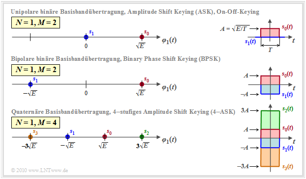
Die Grafik zeigt eindimensionale Signalraumkonstellationen $(N=1)$ für die Basisbandübertragung, nämlich
- (a) binär unipolar (oben) ⇒ $M = 2$,
- (b) binär bipolar (Mitte) ⇒ $M = 2$, sowie
- (c) quaternär bipolare (unten) ⇒ $M = 4$.
Die Grafik beschreibt gleichzeitig die eindimensionalen Trägerfrequenzsysteme
- oben: Zweistufiges Amplitude Shift Keying (2–ASK), auch bekannt als "On–Off–Keying ",
- in der Mitte: Binary Phase Shift Keying (BPSK),
- unten: Vierstufiges Amplitude Shift Keying (4–ASK).
Die dargestellten Signale $s_i(t)$ und die Basisfunktion $\varphi_1(t)$ beziehen sich stets auf den äquivalenten Tiefpass–Bereich.
Im Bandpass–Bereich ist $\varphi_1(t)$ eine auf den Zeitbereich $0 \le t \le T$ begrenzte harmonische Schwingung.
Weitere Anmerkungen:
- In der Grafik rechts sind am Beispiel "Rechteckimpuls" die zwei bzw. vier möglichen Sendesignale $s_i(t)$ angegeben.
- Man kann daraus den Zusammenhang zwischen Impulsamplitude $A$ und Signalenergie $E = A^2 \cdot T$ erkennen.
- Die jeweils linken Darstellungen auf der $\varphi_1(t)$–Achse gelten aber unabhängig von der $g_s(t)$–Form, nicht nur für Rechtecke.
Zweidimensionale Modulationsverfahren
Zu den zweidimensionalen Modulationsverfahren $(N = 2)$ gehören
- M–stufiges Phase Shift Keying (M–PSK),
- Quadratur–Amplitudenmodulation (4–QAM, 16–QAM, 64–QAM, ...),
- Binäres (orthogonales) Frequency Shift Keying (2–FSK).
Allgemein ist bei orthogonaler FSK die Anzahl $N$ der Basisfunktionen $\varphi_k(t)$ gleich der Anzahl $M$ möglicher Sendesignale $s_i(t)$. $N=2$ ist deshalb nur für $M=2$ möglich.
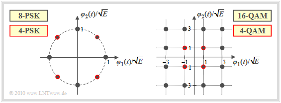
Die Grafik zeigt Beispiele von Signalraumkonstellationen für Zweidimensionale Modulationsverfahren:
- Die linke Grafik zeigt die 8–PSK–Konstellation. Beschränkt man sich auf die rot umrandeten Punkte, so liegt eine 4–PSK (Quaternary Phase Shift Keying, QPSK) vor.
- Die rechte Grafik bezieht sich auf die 16–QAM beziehungsweise – wenn man nur die rot umrandeten Signalraumpunkte betrachtet – auf die 4–QAM.
- Ein Vergleich der beiden Bilder zeigt, dass die 4–QAM mit der QPSK bei entsprechender Achsenskalierung identisch ist.
Die Grafiken beschreiben die Modulationsverfahren sowohl im Bandpass– als auch im äquivalenten Tiefpassbereich:
- Bei der Betrachtung als Bandpass–System ist die Basisfunktion $\varphi_1(t)$ cosinusförmig und $\varphi_2(t)$ (minus–)sinusförmig – vergleiche Aufgabe 4.2.
- Dagegen ist nach der Transformation der QAM–Systeme in den äquivalenten Tiefpassbereich $\varphi_1(t)$ gleich dem energienormierten (also mit der Energie "1") Sendegrundimpuls $g_s(t)$, während $\varphi_2(t)={\rm j} \cdot \varphi_1(t)$ zu setzen ist. Näheres hierzu finden Sie in der Aufgabe 4.2Z.
Aufgaben zum Kapitel
Aufgabe 4.1: Zum Gram-Schmidt-Verfahren
Aufgabe 4.1Z: Andere Basisfunktionen
Aufgabe 4.2: AM/PM-Schwingungen
Aufgabe 4.2Z: Achtstufiges Phase Shift Keying
Aufgabe 4.3: Unterschiedliche Frequenzen
Quellenverzeichnis
- ↑ 1.0 1.1 1.2 Kötter, R., Zeitler, G.: Nachrichtentechnik 2. Vorlesungsmanuskript, Lehrstuhl für Nachrichtentechnik, Technische Universität München, 2008.
- ↑ Wozencraft, J. M.; Jacobs, I. M.: Principles of Communication Engineering. New York: John Wiley & Sons, 1965.
- ↑ Kramer, G.: Nachrichtentechnik 2. Vorlesungsmanuskript, Lehrstuhl für Nachrichtentechnik, Technische Universität München, 2017.


