Contents
General information on LTE transmission technology
In contrast to its predecessor $\rm UMTS$, Long Term Evolution $\rm (LTE)$ uses a variant of the OFDM concept also used by WLAN to systematically divide the transmission resources. The multiple access method $\rm OFDM$ possesses the ability to protect the system against intermittent transmission disturbances, just like the UMTS basic technology $\rm CDMA$.
In principle, it would have been possible to adapt and expand the technologies used in the second and third generations of mobile communications in such a way that they also meet the required specifications for the fourth generation. However, the rapidly increasing complexity of CDMA when received signals on multiple paths made the technical implementation appear to make little sense.
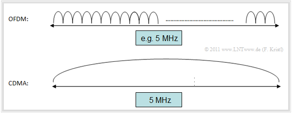
The highly abstracted graphic shows the distribution of the complete bandwidth for individual subcarriers and explains the difference between $\rm CDMA$ (UMTS) and $\rm OFDM$ (LTE).
- In contrast to CDMA, OFDM has many subcarriers, typically even several hundred, with a bandwidth of only a few "kHz" each.
- To achieve this, the data stream is split and each of the many subcarriers is modulated individually with only a small bandwidth.
LTE uses $\rm OFDMA$, an OFDM based transmission technology. Among the reasons for this are [HT09][1]:
- High performance in frequency controlled channels,
- the low complexity in the receiver,
- good spectral properties and bandwidth flexibility, and
- compatibility with the latest receiver and multi-antenna technologies.
In the next section the differences between the multiple access methods "OFDM" and "OFDMA" are briefly explained.
Similarities and differences of OFDM and OFDMA
The principle of "Orthogonal Frequency Division Multiplexing" is explained in detail in chapter Motivation for xDSL of the book "Examples of Communication Systems".
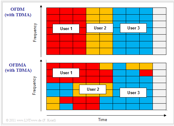
The upper diagram shows the frequency assignment for $\rm OFDM$: This method splits the available frequency band into a large number of narrow–band subcarriers. It is important to note:
- To ensure that the individual subcarriers exhibit as little intercarrier–interference as possible, their frequencies are selected so that they are orthogonal to each other. This means:
- At the center frequency of each subcarrier, all other carriers have no spectral components. The goal is to select the currently most favorable resources for each user in order to obtain an overall optimal result.
- In concrete terms, this also means that the available resources are allocated to the user who can currently do the most with them, adapted to the respective network situation.
- For this purpose, the base station for the downlink to the terminal device measures the connection quality with the help of reference symbols.
The lower diagram shows the allocation at "Orthogonal Frequency Division Multiple Access" $\rm (OFDMA)$. You can see:
- For OFDMA the resource allocation after channel fluctuations is not limited to the time domain as with OFDM, but also the frequency domain is optimally included. Thus the OFDMA resource allocation is better adapted to the external circumstances than with OFDM.
- In order to make optimum use of this flexibility, however, coordination between the base station ("eNodeB") and the terminal equipment is necessary. More on this in chapter General Description of DSL.
Differences between OFDMA and SC-FDMA
There are transmission methods such as
WiMAX, which use OFDMA in both directions. The LTE specification by the 3GPP consortium on the other hand specifies:
- In $\rm Downlink$ (transmission from the base station to the terminal) $\rm OFDMA$ is used.
- In $\rm Uplink$ (from terminal to base station) $\rm SC–FDMA$ ("Single Carrier Frequency Division Multiple Access" ) is used.
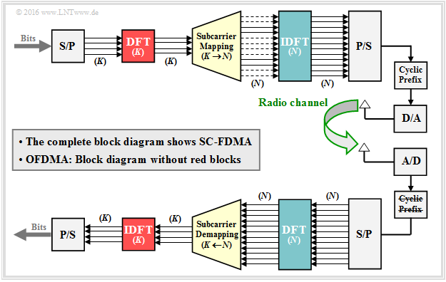
From the graphic you can see that the two systems are very similar. In other words: SC–FDMA is based on OFDMA (or vice versa).
- If you omit the components highlighted in red ${\rm DFT} \ (K)$ and ${\rm IDFT} \ (K)$ from SC–FDMA, you get the OFDMA–System.
- The other blocks stand for Serial/Parallel converter (S/P), Parallel/Serial converter (P/S), D/A converter, A/D converter as well as Add/Remove Prefix.
The signal generation for SC–FDMA works similar to OFDMA, but with small changes that are important for mobile radio:
- The main difference is the additional discrete Fourier transform $\rm (DFT)$. This has to be done on the transmit side directly after the serial/parallel conversion.
- Thus, it is no longer a multi-carrier procedure, but a single-carrier FDMA variant. One speaks of "DFT–spread OFDM" because of the necessary DFT/IDFT operations.
Let us summarize these statements briefly:
$\text{SC–FDMA is different from OFDMA}$ in the following points
[see also the Internet articles "Single-carrier FDMA" (in Wikipedia) and
"Difference between SC-FDMA and OFDMA.html" (from RF Wireless World)]:
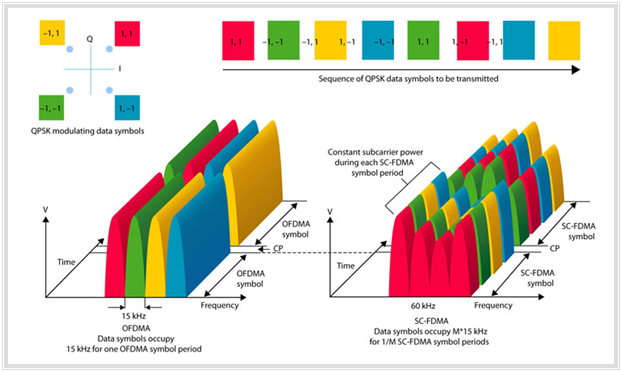
- With SC–FDMA, the data symbols are sent in a group of simultaneously transmitted subcarriers instead of sending each symbol from a single orthogonal subcarrier as with OFDMA. This subcarrier group can then be considered a separate frequency band that transmits the data sequentially. This is where the name "Single Carrier FDMA" comes from.
- While with OFDMA the data symbols directly create the different subcarriers, with SC–FDMA they first pass a discrete Fourier transform (DFT). Thus the data symbols are first transformed from the time domain into the frequency domain before they pass through the OFDM procedure.
One can also describe the difference between "OFDMA" and "SC–FDMA" in such a way:
- In an OFDMA transmission, each orthogonal subcarrier only contains the information of a single signal.
- In contrast, with SC–FDMA, each individual subcarrier contains information about all signals transmitted in this period.
This difference and the quasi–sequential transmission with SC–FDMA can be seen particularly well from the diagram on the right.
This graphic is taken from a PDF document from "Agilent–3GPP".
Functionality of SC-FDMA
Now the SC–FDMA transfer process shall be examined more in detail. The information for this section comes largely from [MG08][2].
The purpose and function of the "Cyclic Prefix" is not discussed here in detail. The reasons for this unit are the same as for OFDM and can be read in the section Cyclic Prefix of the book "Modulation Methods".
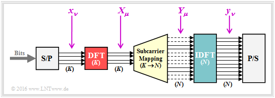
The following description refers to the SC–FDMA transmitter shown here. Note that with LTE the modulation is adapted to the channel quality:
- In highly noisy channels $\rm 4–QAM$ (Quadrature Amplitude Modulation with only four signal space points) is used.
- Under better conditions, the system then switches to a higher-level QAM, up to $\rm 64–QAM$.
The following also applies:
- An input data block consists of $K$ complex modulation symbols $x_\nu$ which are generated at a rate of $R_{\rm Q}\ \big[\rm symbols/s \big]$. The discrete Fourier transform $\rm (DFT)$ generates $K$ symbols $X_\mu$ in the frequency domain, which are modulated on $K$ from a total of $N$ orthogonal subcarriers:
- \[X_\mu = \sum_{\nu = 0 }^{K-1} x_\nu \cdot {\rm e}^{-{\rm j} \hspace{0.05cm}\cdot \hspace{0.05cm} { 2 \pi \hspace{0.05cm}\cdot \hspace{0.05cm} \nu \hspace{0.05cm}\cdot \hspace{0.05cm} \mu }/{K}} \hspace{0.05cm},\]
- The subcarriers are distributed over a larger bandwidth of $B_{\rm K} = N \cdot f_0$ where $f_0 = 15 \ \rm kHz$ is the smallest addressable bandwidth for LTE. Unused channels are shown as dashed lines in the example graphic.
- The channel transmission rate is $R_{\rm C} = J \cdot R_{\rm Q}$ with spreading factor $J = N/K$. This SC–FDMA system could simultaneously process $J$ orthogonal input signals ⇒ number of terminal devices that can be simultaneously connected to this base station. In the case of LTE, for example, the values are $K = 12$ (smallest addressable block) and $N = 1024$.
- According to the so-called "Subcarrier Mapping" which is the assignment of the symbols generated by the DFT to the available subcarriers, the symbols are then mapped to a certain bandwidth, for example $K = 12$ maps to the range of $0 \ \text{...} \ 180 \ \rm kHz$ or to the range of $180 \ \rm kHz \ \text{...} \ 360 \ \rm kHz$.
- The $\rm IDFT$ (highlighted in blue) transforms the output values $Y_\mu$ on the frequency domain in its time representation $y_\nu$. These samples are then transformed by the Parallel/Serial converter into a sequence suitable for transmission.
Different approaches for the Subcarrier Mapping
The following figure illustrates three types of "Subcarrier Mapping". To simplify the representation, we will limit ourselves here to the (very small) parameter values $K = 4$ and $N = 12$.
$\rm DFDMA$ or "Distributed Mapping":
Here the modulation symbols are distributed over a certain range of the available channel bandwidth.
$\rm IFDMA$ or "Interleaved FDMA":
Special form of DFDMA, when the modulation symbols are distributed over the entire bandwidth with equal distances between them.
$\rm LFDMA$ or "Localized Mapping":
The $K$ modulation symbols are assigned directly to adjacent subcarriers. This corresponds to the current 3GPP–specification.
It can be shown that with SC–FDMA the transmitter does not have to be run through the following steps individually
- Discrete Fourier Transform $\rm (DFT)$,
- Subcarrier Mapping,
- Inverse discrete Fourier transform $\rm (IDFT)$ or inverse Fast Fourier transform $\rm (IFFT)$.
Instead, these three operations can be realized together as one single linear operation. The complete and mathematically complex derivation can be found for example in [MG08][2]. Each element $y_\nu$ of the output sequence is then representable by a weighted sum of the input sequence elements $x_\nu$ where the weights are complex-valued.
Hence, instead of the comparatively complicated Fourier transform, the operation is reduced
- to a multiplication with a complex number, and
- the $J$–fold repetition of the input sequence $\langle x_\nu \rangle $.
In Exercise 4.3 the (transmit-side) "Subcarrier Mapping" is considered with more realistic values for $K$ and $N$ and its differences to the "Subcarrier Demapping" (at the receiver) are pointed out.
Advantages of SC-FDMA over OFDM
The decisive advantage of SC–FDMA over OFDMA is its lower "Peak–to–Average Power Ratio" $\rm (PAPR)$ due to its single-carrier structure. This is the ratio of current peak power $P_{\rm max}$ to average power $P_{\rm S}$. $\rm PAPR$ can also be expressed by the Crest factor (quotient of the signal amplitudes). However, the two quantities are not identical.
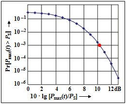
The graphic from the Internet document [Wu09][3] shows in double–logarithmic representation the probability that with 64QAM–OFDM the current power $P_{\rm max}$ is above the average power $P_{\rm S}$. You can see:
- The probability of large "outliers" is small. For example, the average power is only exceeded in $0.1\%$ of time by more than $\text{10 dB}$ ⇒ marked in red.
- Even if such high power peaks are very rare, they still pose a problem for the receiver's power amplifier.
The power amplifiers should be operated in the linear range, otherwise the signal is distorted. Non-linearities arise in particular due to
- intercarrier interference within the signal,
- interference from adjacent channels due to spectrum expansions.
Therefore, OFDM requires the amplifier to operate at a lower power level than its peak power most of the time, which can drastically reduce its efficiency.
- Because one can regard SC–FDMA quasi as single carrier transmission procedures, its PAPR is lower than the one of OFDMA.
- Thus, for example, a so-called "pulse shaping filter" can be used which reduces the PAPR.
The lower PAPR is the main reason why SC–FDMA is used in the LTE uplink and not OFDMA.
- A low PAPR means longer battery life, an extremely important criterion for mobile phones/smartphones.
- At the same time, SC–FDMA offers similar performance and complexity to OFDMA.
- Since a long battery life is less important for the downlink, OFDMA is used here.
$\text{Example 1:}$ We consider an OFDM system with $N$ carriers, all with the same signal amplitude $A$.
After a highly simplified calculation with the same proportionality factor we obtain:
- the maximum signal power is proportional to $(N \cdot A)^2$, and
- the average signal power is proportional to $N \cdot A^2$ .
This results in the peak–to–average power ratio ${\rm PAPR} = N$, since it's the quotient of these two powers. Already with only two carriers this results in ${\rm PAPR} = 2$ which corresponds to $\text{3 dB}$.
- So even with only two carriers the amplifier must always operate $\text{3 dB}$ below the maximum power to avoid signal distortion in case of signal peaks.
- As will be shown below, $\text{3 dB}$ already means a decrease in efficiency to $85\%$.
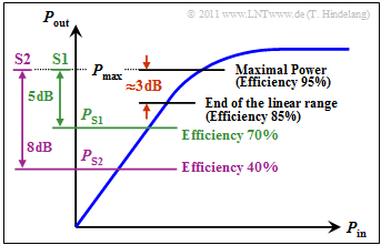
$\text{Example 2:}$ $\rm PAPR$ is directly related to the "Transmit Amplifier Efficiency". Maximum efficiency is achieved when the amplifier can operate in the vicinity of the saturation limit. The graphic shows an example of an amplifier's characteristic curve, i.e. the output power plotted against the input power.
At $\rm PAPR = 1$ $(\text{0 dB})$ one could set the average power $P_{\rm S}$ equal to the allowed peak power $P_{\rm max}$ . According to the characteristic curve $P_{\rm out}/P_{\rm in}$ the amplifier efficiency would be (exemplarily) $95\%$.
Nevertheless, for large $\rm PAPR$ the amplifier must be operated below the saturation limit to avoid too much signal distortion. Here are some numerical examples:
- At $\rm PAPR = 2$ according to the rough calculation on the last example, the average transmit power would have to be chosen $\text{3 dB}$ lower than the allowed power, so that $P_{\rm max}$ would not be exceeded at any time. The efficiency would then decrease to $85\%$ .
- A back–off from $\text{3 dB}$ is usually not sufficient, but in practice values between $\text{5 dB}$ and $\text{8 dB}$, taken from [Hin08][4]. According to the given curve, however, at $\text{5 dB}$ the efficiency already drops to only $70\%$ $($system $\rm S1$, green line$)$.
- With system $\rm S2$ all signal peaks reduced in $\text{8 dB}$ can be transmitted by the amplifier without distortion, but the amplifier efficiency is then only $40\%$. As can be seen in the first graphic in this section, strong distortions still occur about $2\%$ of the time.
- If the average transmit power is $P_{\rm S} = 100\, \rm mW$, then with a $\rm PAPR = 9 \ \Rightarrow \ \text{8 dB}$ the amplifier must work up to $P_{\rm max} = 900\, \rm mW$ without distortion, with $\rm PAPR = 2 \ \Rightarrow \ \text{3 dB}$ on the other hand, only up to $200 \, \rm mW$. The difference between the two amplifiers is an enormous cost factor.
$\text{Conclusion:}$
- OFDM with a large back–off in the uplink would lead to problems, namely extremely short battery life of the mobile devices ⇒ SC–FDMA is used in the LTE uplink.
- In addition, the complexity of SC–FDMA is generally lower than other methods, which means cheaper terminals [MLG06][5]. If the CDMA used in UMTS were extended to the 4G standard, the receiver complexity would increase significantly due to the high frequency diversity in the channel [IXIA09][6].
- However, the frequency domain equalization with SC–FDMA is more complicated than with OFDMA. This is the main reason why SC–FDMA is only used in the uplink. So these complicated equalizers have to be installed only in the base stations and not in the terminals.
Exercices to the Chapter
Exercise 4.3: Subcarrier Mapping
Exercise 4.3Z: Multiple-Access Methods in LTE
References
- ↑ Holma, H.; Toskala, A.: LTE for UMTS - OFDMA and SC-FDMA Based Radio Access. Wiley & Sons, 2009.
- ↑ 2.0 2.1 Myung, H.; Goodman, D.: Single Carrier FDMA – A New Air Interface for Long Term Evolution. West Sussex: John Wiley & Sons, 2008.
- ↑ Wu, B.: Analyzing WiMAX Modulation Quality. PDF Internet document, 2009.
- ↑ Hindelang, T.: Mobile Communications. Lecture Manuscript. Chair of Communications Engineering, TU Munich, 2008.
- ↑ Myung, H.; Lim, J.; Goodman, D.: Single Carrier FDMA for Uplink Wireless Transmission. IEEE Vehicular Technology Magazine, Vol. 1, No. 3, 2006.
- ↑ SC-FDMA - Single Carrier FDMA in LTE. PDF Internet document, 2009.
