Contents
Problem formulation and prerequisites
$\text{Task:}$ This chapter deals with the following problem:
- The $p$–spectral function $Y_{\rm L}(p)$ is given in »pole-zero notation«.
- The »inverse Laplace transform«, i.e. the associated time function $y(t)$ is searched-for, where the following notation should hold:
- $$y(t) = {\rm L}^{-1}\{Y_{\rm L}(p)\}\hspace{0.05cm} , \hspace{0.3cm}{\rm briefly}\hspace{0.3cm} y(t) \quad \circ\!\!-\!\!\!-^{\hspace{-0.25cm}\rm L}\!\!\!-\!\!\bullet\quad Y_{\rm L}(p)\hspace{0.05cm} .$$
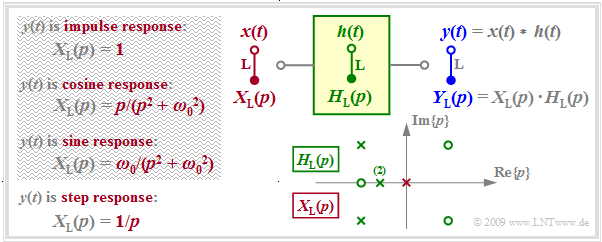
The graph summarizes the prerequisites for this task.
- $H_{\rm L}(p)$ describes the transfer function of the causal system and $Y_{\rm L}(p)$ specifies the Laplace transform of the output signal $y(t)$ considering the input signal $x(t)$ . $Y_{\rm L}(p)$ is characterized by $N$ poles, by $Z ≤ N$ zeros and by the constant $K.$
- Poles and zeros exhibit the properties mentioned in the »last chapter«: Poles are only allowed in the left $p$–half plane or on the imaginary axis; zeros are also allowed in the right $p$–half plane.
- All »singularities« – this is the generic term for poles and zeros – are either real or exist as pairs of conjugate-complex singularities. Multiple poles and zeros are also allowed.
- With the input $x(t) = δ(t)$ ⇒ $X_{\rm L}(p) = 1$ ⇒ $Y_{\rm L}(p) = H_{\rm L}(p)$, the output signal $y(t)$ then describes the »impulse response« $h(t)$ of the transmission system. For this purpose, only the singularities drawn in green in the graph may be used for computation.
- A unit jump function $x(t) = γ(t)$ ⇒ $ X_{\rm L} = 1/p$ at the input causes the output signal $y(t)$ to be equal to the »step response« $σ(t)$ of $H_{\rm L}(p)$ . In addition to the singularities of $H_{\rm L}(p)$, the pole $($shown in red in the graph$)$ at $p = 0$ must now also be taken into account for computation.
- Possible as input $x(t)$ are only signals for which $X_{ \rm L}(p)$ can be expressed in pole-zero notation (see the $\text{table}$ in the chapter »Laplace Transform and $p$–Transfer Function»$)$, for example a cosine or sine signal switched on at time $t = 0$ .
- So, a rectangular signal $x(t)\ \ ⇒ \ \ X_{\rm L}(p) = (1 - {\rm e}^{\hspace{0.05cm}p\hspace{0.05cm}\cdot \hspace{0.05cm} T})/p$ is not possible in the approach described here. However, the rectangular response $y(t)$ can be computed indirectly as the difference of two step responses.
Some results of the theory of functions
In contrast to the $\text{Fourier integrals}$, which differ only slightly in the two directions of transformation, for "Laplace" the computation of $y(t)$ from $Y_{\rm L}(p)$ – that is the inverse transformation – is
- much more difficult than computing $Y_{\rm L}(p)$ from $y(t)$,
- unresolvable or solvable only very laboriously by elementary means.
$\text{Definition:}$ In general, the following holds for the »inverse Laplace transform«:
- $$y(t) = {\rm L}^{-1}\{Y_{\rm L}(p)\}= \lim_{\beta \hspace{0.05cm}\rightarrow \hspace{0.05cm}\infty} \hspace{0.15cm} \frac{1}{ {\rm j} \cdot 2 \pi}\cdot \int_{ \alpha - {\rm j} \hspace{0.05cm}\cdot \hspace{0.05cm}2 \pi \beta } ^{\alpha+{\rm j} \hspace{0.05cm}\cdot \hspace{0.05cm}2 \pi \beta} Y_{\rm L}(p) \hspace{0.05cm}\cdot \hspace{0.05cm} {\rm e}^{\hspace{0.05cm}p \hspace{0.05cm}\cdot \hspace{0.05cm} t}\hspace{0.1cm}{\rm d}p \hspace{0.05cm} .$$
- The integration is parallel to the imaginary axis.
- The real part $α$ is to be chosen such that all poles are located to the left of the integration path.
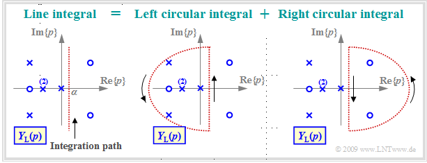
The left graph illustrates this line integral along the red dotted vertical ${\rm Re}\{p\}= α$. This integral is solvable using $\text{Jordan's lemma of complex analysis}$. In this tutorial only a very short and simple summary of the approach is depicted:
- The line integral can be divided into two circular integrals so that all poles are located in the left circular integral while the right circular integral may only contain zeros.
- According to the theory of functions, the right circular integral yields the time function $y(t)$ for negative times. Due to causality, $y(t < 0)$ must be identical to zero, but according to the fundamental theorem of the theory of functions this is only true if there are no poles in the right $p$–half-plane.
- In contrast, the integral over the left semicircle yields the time function for $t ≥ 0$. This encloses all poles and can be computed using the "residue theorem" in a (relatively) simple way, as it will be shown in the next sections.
Formulation of the residue theorem
It is further assumed that the transfer function $Y_{\rm L}(p)$ can be expressed in pole-zero notation by
- the constant factor $K$,
- the $Z$ "zeros" $p_{{\rm o}i}$ $(i = 1$, ... , $Z)$ and
- the $N$ "poles" $p_{{\rm x}i}$ $(i = 1$, ... , $N$).
We also assume $Z < N$.
The number of distinguishable poles is denoted by $I$. Multiple poles are counted only once to determine $I$. Thus, the following holds for the $\text{sketch}$ in the last section considering the double pole: $N = 5$ and $I = 4$.
$\text{Residue Theorem:}$ Considering the above conditions, the »inverse Laplace transform« of $Y_{\rm L}(p)$ for times $t ≥ 0$ is obtained as the sum of $I$ natural oscillations of the poles, which are called the "residuals" – abbreviated as "Res":
- $$y(t) = \sum_{i=1}^{I}{\rm Res} \bigg \vert _{p \hspace{0.05cm}= \hspace{0.05cm}p_{{\rm x}_i}} \hspace{-0.7cm}\{Y_{\rm L}(p)\cdot {\rm e}^{p \hspace{0.05cm}t}\} \hspace{0.05cm} .$$
Since $Y_{\rm L}(p)$ is only specifiable for causal signals, $y(t < 0) = 0$ always holds for negative times.
- In general, the following holds for a pole of multiplicity $l$ :
- $${\rm Res} \bigg \vert _{p \hspace{0.05cm}= \hspace{0.05cm}p_{ {\rm x}_i} } \hspace{-0.7cm}\{Y_{\rm L}(p)\cdot {\rm e}^{p t}\}= \frac{1}{(l-1)!}\cdot \frac{ {\rm d}^{\hspace{0.05cm}l-1} }{ {\rm d}p^{\hspace{0.05cm}l-1} }\hspace{0.15cm} \left \{Y_{\rm L}(p)\cdot (p - p_{ {\rm x}_i})^{\hspace{0.05cm}l}\cdot {\rm e}^{p \hspace{0.05cm}t}\right\} \bigg \vert_{p \hspace{0.05cm}= \hspace{0.05cm}p_{ {\rm x}_i} } \hspace{0.05cm} .$$
- The following is obtained out of it with $l = 1$ for a simple pole as a special case:
- $${\rm Res} \bigg\vert_{p \hspace{0.05cm}= \hspace{0.05cm}p_{ {\rm x}_i} } \hspace{-0.7cm}\{Y_{\rm L}(p)\cdot {\rm e}^{p t}\}= Y_{\rm L}(p)\cdot (p - p_{ {\rm x}_i} )\cdot {\rm e}^{p \hspace{0.05cm}t} \bigg \vert _{p \hspace{0.05cm}= \hspace{0.05cm}p_{ {\rm x}_i} } \hspace{0.05cm} .$$
In the next sections, the "residue theorem" is illustrated by three detailed examples corresponding to the three constellations in $\text{Example 3}$ in the chapter "Laplace Transform and p-Transfer Function":
- So, we consider again the two-port network with an inductance $L = 25 \ \rm µH$ in the longitudinal branch as well as the the series connection of an ohmic resistance $R = 50 \ \rm Ω$ and a capacitance $C$ in the transverse branch.
- For the latter, we again consider three different values, namely $C = 62.5 \ \rm nF$, $C = 8 \ \rm nF$ and $C = 40 \ \rm nF$.
- The following is always assumed: $x(t) = δ(t) \; ⇒ \; X_{\rm L}(p) = 1$ ⇒ $Y_{\rm L}(p) = H_{\rm L}(p)$ ⇒ the output signal $y(t)$ is equal to the impulse response $h(t)$.
Aperiodically decaying impulse response
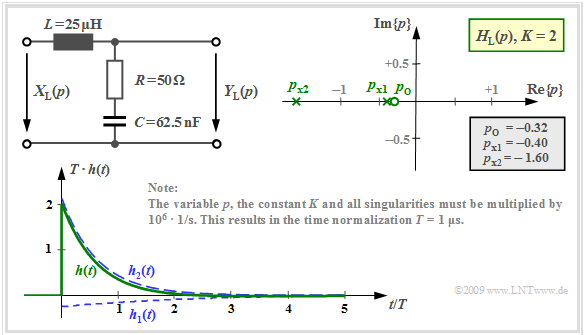
The following is obtained for the $p$–transfer function computed in the section $\text{pole-zero representation of circuits}$ with the capacitance $C = 62.5 \ \rm nF$ and the other numerical values given in the graph below:
- $$H_{\rm L}(p)= K \cdot \frac {p - p_{\rm o }} {(p - p_{\rm x 1})(p - p_{\rm x 2})}= 2 \cdot \frac {p + 0.32 } {(p +0.4)(p +1.6 )} \hspace{0.05cm} .$$
Note the normalization of $p$, $K$ and also of all poles and zeros by the factor ${\rm 10^6} · 1/\rm s$.
The impulse response is composed of $I = N = 2$ natural oscillations. For $t < 0$, these are equal to zero.
- The residual of the pole at $p_{{\rm x}1} =\ –0.4$ yields the following time function:
- $$h_1(t) = {\rm Res} \bigg |_{p \hspace{0.05cm}= \hspace{0.05cm}p_{{\rm x}1}} \hspace{-0.7cm}\{H_{\rm L}(p)\cdot {\rm e}^{p t}\}= H_{\rm L}(p)\cdot (p - p_{{\rm x}1})\cdot {\rm e}^{p \hspace{0.05cm}t} \bigg |_{p \hspace{0.05cm}= \hspace{0.05cm}p_{{\rm x}1}}$$
- $$\Rightarrow \hspace{0.3cm}h_1(t) = 2 \cdot \frac {p + 0.32 } {p +0.4}\cdot {\rm e}^{p \hspace{0.05cm}t} \bigg |_{p \hspace{0.05cm}= \hspace{0.05cm}-0.4}= - \frac {2 } {15}\cdot {\rm e}^{-0.4 \hspace{0.05cm} t} \hspace{0.05cm}. $$
- In the same way, the residual of the second pole at $p_{{\rm x}2} = \ –1.6$ can be computed:
- $$h_2(t) = {\rm Res} \bigg |_{p \hspace{0.05cm}= \hspace{0.05cm}p_{{\rm x}2}} \hspace{-0.7cm}\{H_{\rm L}(p)\cdot {\rm e}^{p t}\}= H_{\rm L}(p)\cdot (p - p_{{\rm x}2})\cdot {\rm e}^{p \hspace{0.05cm}t} \bigg |_{p \hspace{0.05cm}= \hspace{0.05cm}p_{{\rm x}2}}$$
- $$\Rightarrow \hspace{0.3cm}h_2(t) = 2 \cdot \frac {p + 0.32 } {p +1.6}\cdot {\rm e}^{p \hspace{0.05cm}t} \bigg |_{p \hspace{0.05cm}= \hspace{0.05cm}-1.6}= \frac {32 } {15}\cdot {\rm e}^{-1.6 \hspace{0.05cm} t} \hspace{0.05cm}. $$
The graph shows $h_1(t)$ and $h_2(t)$ as well as the sum signal $h(t)$.
- The normalization factor $1/T = 10^6 · \rm 1/s$ is taken into account here so that the time is normalized to $T = 1 \ \rm µ s$ .
- For $t =0$, $T \cdot h(t=0) = {32 }/ {15} -{2 }/ {15}= 2 \hspace{0.05cm}$ is obtained as a result.
- For times $t > 2 \ \rm µ s$, the impulse response is negative (although only slightly and difficult to see in the graph).
Attenuated-oscillatory impulse response
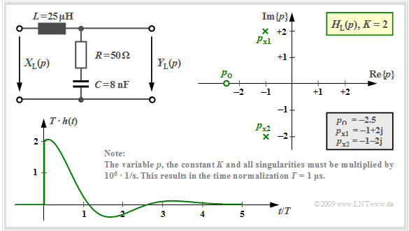
The component values $R = 50 \ \rm Ω$, $L = 25 \ \rm µ H$ and $C = 8 \ \rm nF$ result in two conjugate complex poles at $p_{{\rm x}1} = \ –1 + {\rm j} · 2$ and $p_{{\rm x}2} = \ –1 - {\rm j} · 2$.
- The zero is located at $p_{\rm o} = \ –2.5$.
- $K = 2$ holds and all numerical values are to be multiplied again by the factor $1/T$ $(T = 1\ \rm µ s$).
When applying the residue theorem to this configuration the following is obtained:
- $$h_1(t) = K \cdot \frac {p_{\rm x 1} - p_{\rm o }} {p_{\rm x 1} - p_{\rm x 2}} \cdot {\rm e}^{\hspace{0.05cm}p_{\rm x 1} \cdot \hspace{0.05cm}t} $$
- $$\Rightarrow \hspace{0.3cm}h_1(t) = 2 \cdot \frac {-1 + {\rm j}\cdot 2 +2.5} {(-1 + {\rm j}\cdot 2) - (-1 - {\rm j}\cdot 2)}\cdot {\rm e}^{\hspace{0.05cm}p_{\rm x 1} \cdot\hspace{0.05cm}t}$$
- $$\Rightarrow \hspace{0.3cm}h_1(t) = 2 \cdot \frac {1.5 + {\rm j}\cdot 2} {{\rm j}\cdot 4}\cdot {\rm e}^{\hspace{0.05cm}p_{\rm x 1} \cdot\hspace{0.05cm}t}= (1 - {\rm j}\cdot 0.75)\cdot {\rm e}^{-t}\cdot {\rm e}^{\hspace{0.03cm}{\rm j}\hspace{0.05cm}\cdot \hspace{0.05cm} 2t} \hspace{0.05cm} ,$$
- $$ h_2(t) = K \cdot \frac {p_{\rm x 2} - p_{\rm o }} {p_{\rm x 2} - p_{\rm x 1}}\cdot {\rm e}^{\hspace{0.05cm}p_{\rm x 2} \hspace{0.03cm}\cdot \hspace{0.05cm}t} $$
- $$\Rightarrow \hspace{0.3cm} h_2(t) = 2 \cdot \frac {-1 - {\rm j}\cdot 2 +2.5} {(-1 - {\rm j}\cdot 2) - (-1 + {\rm j}\cdot 2)}\cdot {\rm e}^{\hspace{0.05cm}p_{\rm x 2} \hspace{0.03cm}\cdot\hspace{0.05cm}t} $$
- $$\Rightarrow \hspace{0.3cm}h_2(t) =2 \cdot \frac {1.5 - {\rm j}\cdot 2} {-{\rm j}\cdot 4}\cdot {\rm e}^{\hspace{0.05cm}p_{\rm x 2} \hspace{0.03cm}\cdot\hspace{0.05cm}t}= (1 + {\rm j}\cdot 0.75)\cdot {\rm e}^{-t}\cdot {\rm e}^{\hspace{0.03cm}-{\rm j}\hspace{0.05cm}\cdot \hspace{0.05cm} 2t} \hspace{0.05cm} . $$
Using $\text{Euler's theorem}$ the following is obtained for the sum signal:
- $$h(t) = h_1(t) + h_2(t)\hspace{0.3cm} \Rightarrow \hspace{0.3cm}h(t) = {\rm e}^{-t}\cdot \big [ (1 - {\rm j}\cdot 0.75)\cdot (\cos() + {\rm j}\cdot \sin())+ + (1 + {\rm j}\cdot 0.75)\cdot (\cos() - {\rm j}\cdot \sin())\big ]$$
- $$\Rightarrow \hspace{0.3cm}h(t) ={\rm e}^{-t}\cdot \big [ 2\cdot \cos(2t) + 1.5 \cdot \sin(2t)\big ]\hspace{0.05cm} . $$
The graph shows the attenuated-oscillatory impulse response $h(t)$ attenuated by ${\rm e}^{–t}$ for this pole–zero configuration.
Critically attenuated case
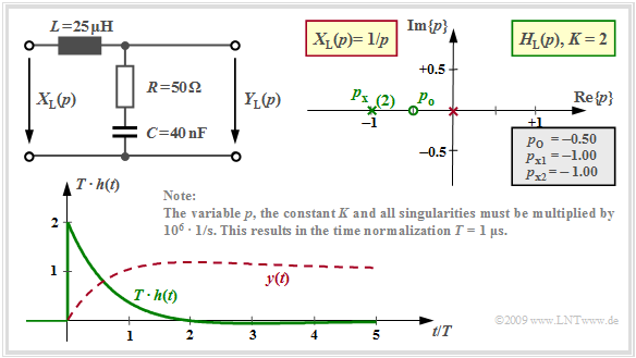
With $R = 50 \ \rm Ω$, $L = 25 \ \rm µ H$ and $C = 40 \ \rm nF$ we get the so-called "critically attenuated case":
- $$H_{\rm L}(p)= K \cdot \frac {p - p_{\rm o }} {(p - p_{\rm x })^2}= 2 \cdot \frac {p + 0.5 } {(p +1)^2} \hspace{0.05cm} .$$
The capacitance value $C = 40 \ \rm nF$ is the smallest possible value for which there are just real pole places.
These coincide, that is $p_{\rm x} = \ -1$ is a double pole place. The time function is thus according to the residue theorem with $l = 2$:
- $$h(t) = {\rm Res} \bigg |_{p \hspace{0.05cm}= \hspace{0.05cm}p_{ {\rm x} } } \hspace{-0.7cm}\{H_{\rm L}(p)\cdot {\rm e}^{p t}\}= \frac{ {\rm d} }{ {\rm d}p}\hspace{0.15cm} \left \{H_{\rm L}(p)\cdot (p - p_{ {\rm x} })^2\cdot {\rm e}^{p \hspace{0.05cm}t}\right\} \bigg |_{p \hspace{0.05cm}= \hspace{0.05cm}p_{ {\rm x} } } = K \cdot \frac{ {\rm d} }{ {\rm d}p}\hspace{0.15cm}\left \{ (p - p_{ {\rm o} })\cdot {\rm e}^{p \hspace{0.05cm}t}\right\} \bigg |_{p \hspace{0.05cm}= \hspace{0.05cm}p_{ {\rm x} } } \hspace{0.05cm} .$$
Using the "product rule" of differential calculus, this gives:
- $$h(t) = K \cdot \left [ {\rm e}^{p \hspace{0.05cm}t} + (p - p_{ {\rm o} })\cdot t \cdot {\rm e}^{p \hspace{0.05cm}t} \right ] \bigg |_{p \hspace{0.05cm}= \hspace{0.05cm}-1} = {\rm e}^{-t}\cdot \left ( 2 - t \right) \hspace{0.05cm} .$$
The graph shows this impulse response (green curve) in normalized representation. It differs only slightly from the one with the two different poles at $-0.4$ and $-1.6$ .
The signal drawn in red ⇒ $y(t) = 1 - {\rm e}^{-t} + t \cdot {\rm e}^{-t}$ results when a step function is also considered at the input ⇒ "step response".
To calculate the step response $\sigma(t) = y(t)$ one can alternatively
- consider an additional pole at $p = 0$ in the residual calculation (marked in red), or
- form the integral over the impulse response $h(t)$.
Partial fraction decomposition
Prerequisite for the application of the residue theorem is that there are less zeros than poles ⇒ $Z$ must always be smaller than $N$ .
If, on the other hand, as in the case of a high-pass filter $Z = N$, then
- is the limit of the spectral function $H_{\rm L}(p)$ for large $p$ not equal to zero,
- if the associated time signal $y(t)$ also contains a $\text{Dirac delta functions}$,
- the residue theorem fails and a $\text{partial fraction decomposition}$ must be performed.
The procedure is to be clarified exemplarily for a high-pass of first order.
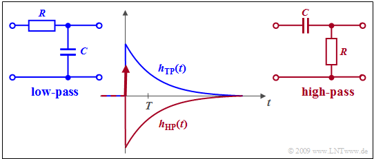
$\text{Example 1:}$ The $p$-transfer function of a "first-order RC high-pass filter" can be transformed by splitting off a constant as follows:
- $$\frac{p}{p + RC} = 1- \frac{RC}{p + RC}\hspace{0.05cm} .$$
Thus, the high-pass impulse response is:
- $$h_{\rm HP}(t) = \delta(t) - h_{\rm TP}(t) \hspace{0.05cm} .$$
The graph shows
- as a red curve the high–pass impulse response $h_{\rm HP}(t)$,
- as a blue curve the impulse response $h_{\rm TP}(t)$ of the equivalent low-pass.
The Dirac delta function is the Laplace transform of the constant value $1$,
while the second function to be subtracted gives the impulse response of the equivalent low-pass filter, which is given by the residue theorem with
- $$Z = 0,\hspace{0.2cm} N =1,\hspace{0.2cm} K = RC.$$
Exercises for the chapter
Exercise 3.5: Circuit with R, L and C
Exercise 3.5Z: Application of the Residue Theorem
Exercise 3.6: Transient Behavior
Exercise 3.6Z: Two Imaginary Poles
Exercise 3.7: Impulse Response of a High-Pass Filter
Exercise 3.7Z: Partial Fraction Decomposition
